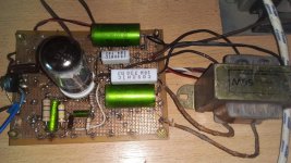
Great good news: the thing said its few words and musical notes. I made a rudimentary audio amplifier with a 6BF11 using the pentode section as preamp and a 220/12V as output transformer and could listen the few firsts sounds. Very distorted because the bw seems too low but it is promising. I feel very happy.
Attachments

One more question. I'm using thr Foster Seeley detector. How is the correct manner to adjust the coupling of the two windings of the transformer (l refer to the two tuned windings, the 90° is naturally wound over the primary with as close coupling as factily possible).
All the ones I've ever seen have had the windings spaced apart about half a inch, not overlaid. It's the slug that achieves the coupling. I'm sure this is covered in the RDH.
This page on the math of impedance matching might be enough: https://www.electrical4u.com/impedance-matching/
But a calculator based on (part) of that math is much simpler: https://www.eeweb.com/tools/pi-match/
Keep in mind that apart from matching at the required frequency, a pi filter also is low pass.
But a calculator based on (part) of that math is much simpler: https://www.eeweb.com/tools/pi-match/
Keep in mind that apart from matching at the required frequency, a pi filter also is low pass.
Many thanks to both. Pi filters were used in my firsts tx at 3500khz when I got my LW1DSE calsign about 1987, using a 6DQ6 as output stage. A single 410pF, a coil and a 3 x 410pF paralleled. So l know them from my early days in radio. Let me some time to experiment, read and learn.
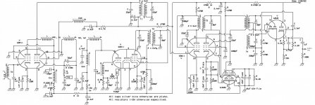
This is an approximate schematic of the entire tuner. Some values may syill be changed. The vast majority of the caps are silver mica except the film units in the cathode follower stage and limiter; and the plate units at cathode decoupling and heaters. Resistor 1/2 watt except two.
If somebody wants the schematic in expresspcb format, it is available; but sincerely I unknow if libraries are also needed.
There is also an undocumented PSU which consists in a 220V transformer to 440V center tapped, an EZ81 rectifier and a 6FD7 wired as series regulator to give about 140DCV well filtered from ripple and an CLC filter between them.
Cx1, Cx2 and Cx3 are the ganged variable tuning capacitor whose exact value is unknown.
Attachments
Can you talk about the discriminator design? Why you went for a tertiary winding, and 470k diode loads?
The Foster Seeley discriminator uses 2 coils like in the other IFTs, probably closer because bandwidth must be higher. The hot side of the primary is coupled to the center of the secondary coil with a capacitor, and the center is connected via an RF choke to the center of the output RC (load) network: see https://www.fmuser.net/wap/content/?6846.htmlOne more question. I'm using thr Foster Seeley detector. How is the correct manner to adjust the coupling of the two windings of the transformer (l refer to the two tuned windings, the 90° is naturally wound over the primary with as close coupling as factily possible).
Bandwidth of the discriminator is determined by coupling primary - secondary, and the load network (lower R ---> higher bandwidth).
The 470K are tentative. I saw there values from 47K to 100K. The use of capacitive coupling from the primary or the use of a terriary winding are the same from the performance point of view, but the cap occupies some space in the shielding cans that I haven't. And the risk with silvered mica cap that a short circuit thanks to silver migration destroy the 6BV8 diodes.
As you can readily deduce, l have the knowledge but not the practice, thus l am learning on the walk.
As you can readily deduce, l have the knowledge but not the practice, thus l am learning on the walk.
Highest diode load I ever say is 120k, which delivered well over 2VRMS. You are going to get 4 times that, if indeed it works at all.
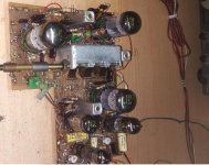
This is a general layout of the tuner. Some important items are explained inside it. The general way of the signal is U shaped, say, input is close to output what in general isn't good. But as you can see, the thing grows up a bit chaotically as new stages were added. Obviously more care will be taken in the final artwork.
Attachments
Got it!Highest diode load I ever say is 120k, which delivered well over 2VRMS. You are going to get 4 times that, if indeed it works at all.
Attachments
Question for mods (if anyone here): why when uploading the pic it appears 90deg rotated?. Mistery...
I'm not a mod, but chances are it is related to the EXIF header that was added to the JPEG standard: it features an orientation field and is supported by some programs, but not by others. There is a free program called jhead that can fix these issues.Question for mods (if anyone here): why when uploading the pic it appears 90deg rotated?. Mistery...
Last edited:
Again: tertiary is because in the shielding cans (square 14mm side) there isn't enough place to 3 or more silver mica capacitors. As I have lots of winding wires, it is more easy for me to wind a small coil than to add a cap inside the can. Also, some mica capacitors have silver migration that shorts the cap. I saw several of them inside K-Trans IF transformers with embedded capacitors in the plastic base.You're not answering the questions. Why the tertiary winding, and why 470K?
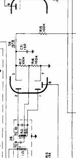
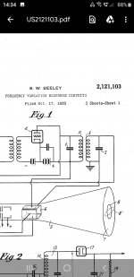
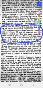
Regarding 470K resistors, this value seemed interesting until l found commercial circuits in the Beitman manuals at worldrahistory.com where I found that this value is too large. Seeley in his patent say values for load resistor of between 500K and 1Mohm; look below.
Attachments
Last edited:
Indeed, because otherwise someone could get a patent on a modification: https://patents.google.com/patent/US4254378A/enWeird that he is so specific in a patent, patents are usually as generic as possible.
- Home
- Source & Line
- Analogue Source
- A new FM tuner with Compactron Tubes