Many thanks to all participants. It is comforting to see people interested in RF topics too.
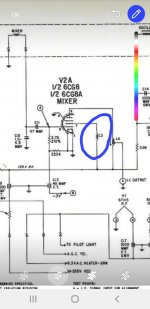
Here is a partial schematic of the front end with both compactron tubes, 6BN11 RF amp and mixer and 6BD11 oscillator and 1º IF. There still unused a triode section, it will be used further for AFC.
There are two test points, one at the mixer's grid, another in the oscillator grid. Both must be highly unlinear, the first to generate a severe over driven in order to obtain high conversion efficiency, and the other to attain high efficiency of the oscillator. As a consequence, measuring grid rectification is an estimable parameter to see how are they doing its job. This sounds rare for audiophiles, but in RF things are different. As always, some values and the general circuit may change.
Attachments


Another variable (useful for experimentation) is the mixer's screen grid voltage: the mixer might perform better with a lower Vg2 than is used as RF (IF) amp. Grid- current driven audio amps require an extra tube as DC coupled driver so unpopular while tubes were expensive. It once was an interesting topic in Linear Audio Vol. 6 & 8. Using a modern opamp to drive the grid could further improve performance, especially when using high gm tubes like 6P15 / SV83 / E130L.
Agree 100%. Observe in the schematic a 4.7K (provisory) screen grid droping resistor and no cathode bias. Also, l saw in TV tuner patricularly later ones, that the screen grid is live for RF thanks to small choke, sometimes some turns of wire or a ferrite bead. I learned that it causes regeneration in the control grid thanks to the presence a transfer negative conductance. It helps improving the mixer behavior.
Attachments
In my case, at 12MHz IF value gives the image about 24MHz, well outside band (20MHz). The 9th harmonic of 12MHz is about 108MHz, in the border. My problem may be the 8th, at 96MHz.With such an amount of nearby transmitters, it's good practice to choose an IF high enough to guarantee absence of image reception. In that respect, higher is better. The problem arises with limiting, when harmonics leak into the input circuits. In my tube receivers with 10.7 IF, major culprit was the 9th, resulting in lower sensitivity at around 96.3 MHz. It was one of the reasons to change topology to 2nd conversion with "low enough" 2nd IF.
Also I am unsure if to place an IF trap at the input of the RF amplifier. Perhaps at the RF's cathode.
Interesting detail, pentode mixer improvement with screen inductor. Is there an article describing the effect in a verifiable way?
IF harmonics were much less of a problem in semiconductor radios. One reason, smaller wires carrying IF voltage (so less radiation) and the other, lower voltages. Screening helps only to a certain extent, running the limiters at the lowest possible supply voltage might be a worthwhile tradeoff with detector output (extra AF amp is easier than a trial & error course of rigid screening).
IF entering via the antenna used to be quite a nuisance. The best solution was the insertion of a high-pass filter at the antenna input, providing the required IF attenuation. Quite often the tuner wasn't the culprit but the issue appeared to be one of improper grounding: the current running from (connected via long transmission line) antenna to ground produced enough signal on the IF input to swamp the IF amp and action on the tuner (even disconnecting power) had zero effect.
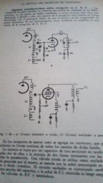
The first time I read about screen regeneration was in an argentine book from Algarra & Rodríguez specifically about TV's of the tube B&W era several years ago. But recently I found that this was known in the Terman's books and an magazine article I downloaded and printed. Let me some time to found it.Interesting detail, pentode mixer improvement with screen inductor. Is there an article describing the effect in a verifiable way?
Attachments
See for example US2750450 assigned to J. C. Achenbach particularly the paragraph at column 4th from line 7 to 23; and US2881265 by P. C. Swierczac pages 5-6 and 7-8. But the first of both is more juicy for my taste.
Another intetesting readings can be found in the article "Input conductance neutralization" by H. R. Freeman in Electronics october 1939 and in the Langford-Smith's Radio designer's hadbook (Radiotron).
They are available at americanradiohistory.com and in the case ofthe LS handbook, l have an original copy.
The patents mentioned are freely available at patents.google.com
Last edited:
My version of Radio Engineers' Handbook is from 1943, no mention made of regeneration via screen grid inductor. But the chapter on FM receivers ends with mentioning frequency feedback.
Of course I only can speak for myself. Anyway, my interest in electronics was launched by an educative toy called »Radiomann« that I received as a Christmas present from my parents in 1970. Here's a link to a German language covering this toy, for those who are interested. As it's name implies, it's prime themes were centered around radio and bradcasting. Hence my own roots 😉.Many thanks to all participants. It is comforting to see people interested in RF topics too.
Best regards!
Interesting the link posted. Wonderful pics. I don't understand German. (Between us, Spanish neither 🙄 ).
A book I like is Vacuum-tube Circuits And Transistors, Lawrence Baker Arguimbau (engineer at McIntosh in the early FM period) and another guy.
https://www.abebooks.com/servlet/SearchResults?kn=Arguimbau, Lawrence Baker
He was an interesting thinker, and fun writer. I was not sure I got my $20 worth, and it sells at ~~$30 now (and we know shipping into Argentina is brutal). Fortunately you can read it online now, by the page or PDF.
https://archive.org/details/in.ernet.dli.2015.125292/page/n5/mode/2up -- the PDF is 43 Megs
I thank you for your suggestion. I took a look to the book Radio Receivers Design by Sturley. But looks a bit boring because excessive (in my opinion) maths. My apologies for too many oo's 😎
A question for those with experiene in this topic: l want to make the input from antena to first grid via an autotransformer, say, a taped inductor tuned with one section of the gang. In practice, how do l find the proper taping point, not having complex instrumental like network analizer and the like? My oscillo is only 40MHz bw.
Many thanks in advance.
Many thanks in advance.
Last edited by a moderator:
Because the major use of tubes has become audio, data concerning RF design has been omitted in (too) many cases. One example where some of that data still is present is the Philips E188CC: input resistance (loading of input circuit) = 3k @ 100 MHz and Req = 250 R (measured at 45 MHz). When using 75R coax, the turns ratio for best SWR (and power gain) would be 6. But that results in maximum damping of the input LC and would only be acceptable when the RF stage is followed by enough selectivity. Hence the standard compromise is to use a tap for the grid at 1/2 of the turns and then tap the 1st turn somewhere for best S/N at a weak enough but steady signal. In that case the inductance of the lead to the input connector is a major issue, which I had to measure and enter in simulation of a FM semiconductor front end for correct results.
TV RF tubes usually are measured at 45 MHz and the rule of the thumb often applied was that @ 100 MHz the load resistance has to be divided by up to 5 so is quite low (~416R for the E810F). Hence for maximum selectivity from 2 RF tuned LCs a wideband (input) grounded grid amp (EC86, 6S4PEV etc.) remains the best solution.
TV RF tubes usually are measured at 45 MHz and the rule of the thumb often applied was that @ 100 MHz the load resistance has to be divided by up to 5 so is quite low (~416R for the E810F). Hence for maximum selectivity from 2 RF tuned LCs a wideband (input) grounded grid amp (EC86, 6S4PEV etc.) remains the best solution.
Isn't there a formula to calculate the impedance of a LC resonant circuit? With this, the inductor's taps could be calculated to match the 75 Ω antenna as well as the tube input impedance, at least in the geometric middle of the FM range.
Best regards!
Best regards!
When you have a resistance R and you put a reactance X in series with it, you get an impedance R + j X. The reciprocal is an admittance G + j B with G = R/(R2 + X2) and B = -X/(R2 + X2). Tune out the susceptance B and you have transformed R into a resistance 1/G = (R2 + X2)/R.
This is a useful calculation when you want relatively wideband matching (single series inductor for the series reactance, capacitor shunting the high-impedance side for tuning out the susceptance) and it may also be useful for narrowband matching when you don't mind having to tune two tanks. I never looked at the narrowband case with a single tank.
This is a useful calculation when you want relatively wideband matching (single series inductor for the series reactance, capacitor shunting the high-impedance side for tuning out the susceptance) and it may also be useful for narrowband matching when you don't mind having to tune two tanks. I never looked at the narrowband case with a single tank.
The equivalent resistance (non disipative) of a parallel LC circuit is sqrt(L/C).
I though in a pi and an L circuit, but both need a series capacitance with the gang which makes difficult tracking with Mixer Grid and Oscillator.
Somewhere i read that moreover of providing gain, the real usefulness of the RF amplifier is to block radiation from LO. RF gains os 5 to 10 seems to be usual as Langford Smith say. Which is your opinion?
- Home
- Source & Line
- Analogue Source
- A new FM tuner with Compactron Tubes