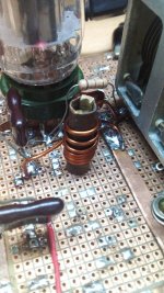
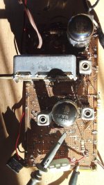
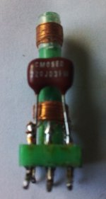
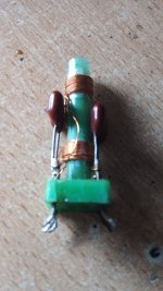
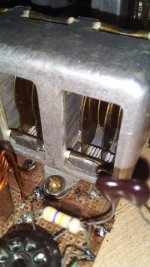
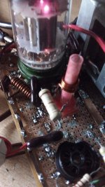
Almost surely this is the final artwork of the oscillator coil. Above is the tuned grid winding, 3 turns 1.2mm enamel copper wire. Turns separated by a wire diameter.
Below plate tickler coil. 4 turns 0.9mm close winding as close to grid coil as possible. The bobbin is a piece of screwed tube from vintage VIX transformer. Inside it is a brass slug cutted from a screw and sloted to enable adjustment via a screwdriver.
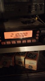
Still no frequency centered, as is it covers from 105MHz to 127MHz with bias from -2,5V to -4V respectively. Anode voltage from 84 to 60V obtained from regulated 140DCV via a 47K 1W protective resistor.
Once temperature reachs an equilibrium, mantains freq. very good.
Satisfied !!!
Below plate tickler coil. 4 turns 0.9mm close winding as close to grid coil as possible. The bobbin is a piece of screwed tube from vintage VIX transformer. Inside it is a brass slug cutted from a screw and sloted to enable adjustment via a screwdriver.
Still no frequency centered, as is it covers from 105MHz to 127MHz with bias from -2,5V to -4V respectively. Anode voltage from 84 to 60V obtained from regulated 140DCV via a 47K 1W protective resistor.
Once temperature reachs an equilibrium, mantains freq. very good.
Satisfied !!!
Attachments


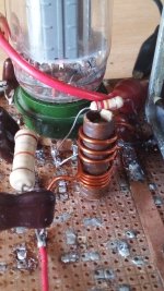
This is the final appearance of the oscillator coil. Legs of to coil were cut to the minimal size compatible with razonable separation from the tube. Grid leak increased to 22K and plate dropping resistor reduced to 18K. Grid voltage varies from -3.5V to -4.15V while frequency is changed from 109.8Mcs to 131.2Mcs and plate voltage does from 96.5 down to 95V in the same conditions. This means (150V - 95V)/ 18K = 3mA anode current and about 300mW power input to oscillator. Looks good.
Microfonics greatly reduced too.
Microfonics greatly reduced too.
Attachments
I moved the IF amplifier to the main protoboard and added the new 6BD11 pentode section to make a 3 step amplifier with 4 doubly tuned transformers; 3 of them of similar kind and the 4th is obviosly different, with 1 more winding for the Foster Seeley or phase discriminator detector. Below, some pics. The gain is very high, but thanks to the neutralizing of the stages individually, the amplifier doesn't oscillate.
Observe exyremely loose coupling but the large output signal, that is attenuated by the 10x of the oscillo tip plus a voltage divider between screen pseudo-decoupling and tuning cap, in a ratio of 22pF to 820pF.
Satisfied once !!!
Observe exyremely loose coupling but the large output signal, that is attenuated by the 10x of the oscillo tip plus a voltage divider between screen pseudo-decoupling and tuning cap, in a ratio of 22pF to 820pF.
Satisfied once !!!
Attachments

Btw, referring to my posts #200 and #205 from abouit a month ago: The short wasn't from the middle FM section to ground, but to the adjacent AM section instead. Obvoiusly I had lost some recollection 🙄. Anyway, yesterday I discharged an old, fully charged 4700 µF/63 V electrolytic between both sections and now the short is gone, without any fireworks, btw. The three FM sections' capacitance is 36 pF each with the plates fully in. My humble measurement equipment sadly doesn't allow reliable values for their minimum capacitance. I will keep the unit for some upcoming project.
Sorry for having captured the thread and for possible annoyance. Best regards!
Sorry for having captured the thread and for possible annoyance. Best regards!
Don't woory, Sir. Your comments are welcome.
More (newer) pics.
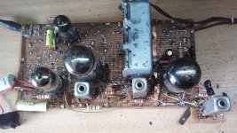
I moved the IF stage to the same protoboard as the gang and the oscillator. The front end is temporarily suspended until the IF section be fully tested and adjusted.
The IF stage now is composed by 3 pentode amplifiers coupled by doubly tuned transformers although they aren't still adjusted as the detector isn't still made. The first stage is the pentode unit inside 6BD11 followed by the high gm unit of the 6BW11 and finally the lower gm unit of it.
Trafos are probably largely undercoupled still, but in any case very high amplification is obtained free of oscillations thanks to the neutralization of each individual step using screen neutralization above explained. Refering to pics, the RF output at the last screen is displayed in the oscillogram, but consider the 10x att of the tip plus a voltage attenuation in ratio of the tunning capacitance (22pF mica silvered) to the cuasi-screen-decoupling (of 820pF mica silver) giving an extra attenuation of 820 to 22 or abut 40 times. So the level at the plate is very large. In the other hand, see the very poor coupling between the generator to the first grid with about 6mm of separation. Pics taks by their own.
More (newer) pics.
I moved the IF stage to the same protoboard as the gang and the oscillator. The front end is temporarily suspended until the IF section be fully tested and adjusted.
The IF stage now is composed by 3 pentode amplifiers coupled by doubly tuned transformers although they aren't still adjusted as the detector isn't still made. The first stage is the pentode unit inside 6BD11 followed by the high gm unit of the 6BW11 and finally the lower gm unit of it.
Trafos are probably largely undercoupled still, but in any case very high amplification is obtained free of oscillations thanks to the neutralization of each individual step using screen neutralization above explained. Refering to pics, the RF output at the last screen is displayed in the oscillogram, but consider the 10x att of the tip plus a voltage attenuation in ratio of the tunning capacitance (22pF mica silvered) to the cuasi-screen-decoupling (of 820pF mica silver) giving an extra attenuation of 820 to 22 or abut 40 times. So the level at the plate is very large. In the other hand, see the very poor coupling between the generator to the first grid with about 6mm of separation. Pics taks by their own.
Attachments

Only wanting to thanks Mooly and Pano for the change of the thread tittle. As l explained them, the permeability tuning mechanics has been disassembled, and having owned and modified the 3 gang tuning cap. with favorable resuts, the permeability tuning will not longer be played.
This is a prototype of the ratio detector transformer. Upper (far from the base) is the secodary moovable to and from the primary, close to the bottom. Secondary will feed the 6AL5 double diode while the primary will be feed by the unit 2 (lower Gm according to the datasheet) of 6BD11.
Tuning cap of the primary is wired but seconary no, in order to show the transformer better.
Primary is 24T of 0.22mm enamel Cu wire while the untuned secondary is wound directly over it. Tuning capacity is 22pF mica. Tuned secondary is the same (# of turns and diameter), centre taped and wired in series with untuned secondary. Remember (once more) that my IF is 12MHz in place of the 10.7MHz took as standard.
Attachments

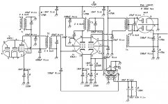
This is an approximate schematic of the IF strip as it is. Some components may vary. Particularly, the secondary tuning cap were reduced to 10pF mica, because of the added capacitance of the 6JU8A diodes, close to 5pF each section.
Note also, that initially I shall try the Foster Seeley (Phase discriminator) detector in place of the ratio detector, although the transformer design is similar. So changing from one to other is only a question of reorder peripheral components around 6AL5 diode and T4.
Note also, that initially I shall try the Foster Seeley (Phase discriminator) detector in place of the ratio detector, although the transformer design is similar. So changing from one to other is only a question of reorder peripheral components around 6AL5 diode and T4.
Attachments
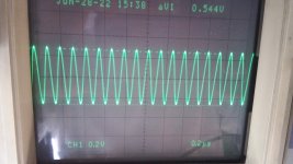
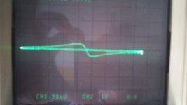
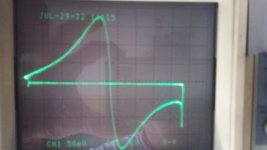
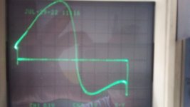
Good news. The Foster Seeley detector is performing well. Below 3 oscillograms taken at 12MHz with small BW. Note that the tuned circuits are tuned but coupling coefficients aren't so the perform isn't optimal. Some troubles associated with neutralizing capacitors (those wired between screen grid and earth) were found and removed. Unsure why the the image got distorted at higher signal levels.
The signal of the 3 oscillograms were adjusted closing the coupling of the generator signal, first with no connection but about 1cm from gen cable and first grid, second with the alligator clip close to the grid and last wired through a 2pf cap. In the first pic limiting isn't operative (signal level decreased until no signal is rectified) but in the following two it is active. Next steep will be the RF amplifier and first detector.
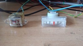
Also added a 6J6 driving a zero center microammeter to see the signal deviation and another microammeter in series with the limiter detector to reletively measure signal strenght (S-meter).
The signal of the 3 oscillograms were adjusted closing the coupling of the generator signal, first with no connection but about 1cm from gen cable and first grid, second with the alligator clip close to the grid and last wired through a 2pf cap. In the first pic limiting isn't operative (signal level decreased until no signal is rectified) but in the following two it is active. Next steep will be the RF amplifier and first detector.
Also added a 6J6 driving a zero center microammeter to see the signal deviation and another microammeter in series with the limiter detector to reletively measure signal strenght (S-meter).
Attachments
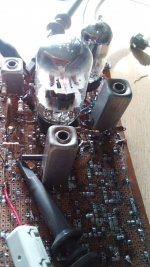
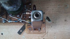
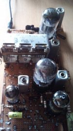
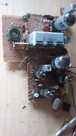
Yesterday l added a second piece of protoboard pcb in order to give place to the RF amplifier. This is the ugliest look. I shall use a 6BF11 double triode (gm~8mS) as cascode RF amplifier and the pentode unit as mixer. Thus, the pentode inside the 6BD11 will continue being the first IF stage, properly neutralized gives me lots of RF gain.
Perhaps the distance between the 6BF11 pentode and the first IF transformer is a bit large (10cm) but l shall use screened cable to do it and the internal cable capacitance, substracted from the tuning cap inside the IF can (22pF). Let me see what happens.
The flat piece of brass in the corner of the two pcbs is grounded and is there to make good grounding of the ground clip of the oscilloscope tip (apologize for the redundancy) 🙄
Attachments
The 6BH11 as cascode amplifier was a resounding failure. It can't be stopped to oscillate at a strange square wave syncronized with the 50Hz line. Possible causes are the lack of shielding between units and heater leackage to cathodes. Using both sections as top and bottom triodes alternatively (both combinations tested with same results). So she was discarded. Now the things go for the way of the original cascode version.
I shall continue posting advances (or not) 😏.
I shall continue posting advances (or not) 😏.
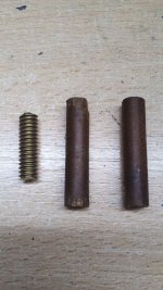
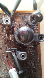
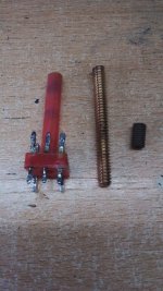
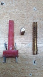
Seeking in my junk, found more coil formers like those used forthe IF transformers, then I thought in using them for the RF front end, replacing unknown and weak carbonil slugs (several broken inside the coil former when trying to adjust them) by small pieces of brass having the same screw dimensions. Below, are shown them.
Also, in order to increase the gain of the stages, l removed one more thinker from the gang capacitor, more precisely from its stator blocks. Then only 2 sheets are in the stator and 4 in the rotor.
For the same frequency, there are infinite combinations of LC constants f= 1/(2 × pi × sqrt(L × C)) but the gain of cascodes and pentodes reach a gain of Av = gm × Zl where Zl is the load impedance, which is controlled by the formula Zl = sqrt (L / C). Thus, doubling the L and halving the C values; Zl is doubled and also gain.
So, removing the sheet of the gang and increasing inductance will give more Zl. As a second benefit, coil former diameter is smaller, and small sizes is good for RF.
(Note: sqrt is the square root or 0.5 power.)
Attachments
Osvaldo, your F-S detector curves aren't good enough yet. The 2nd picture is the best, but the middle of it should be ruler-straight across 318KHZ. This indicates that you don't have the coupling quite right. Straightness corresponds to linearity.
You re right. But as I said, coupling between tuned windings in IF transformers aren't yet adjusted. These pics were taken as they were when finished of mounting in the PCB.
Many thanks for your words. I'll take into account when adjusting k's and M's.
Many thanks for your words. I'll take into account when adjusting k's and M's.
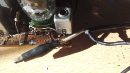
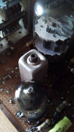
This is the new oscillator with new oscillator coil and topology. It now is of the TNT kind (Tuned Not-Tuned) with the tank at the plate of the triode and the grid maintained live for RF by the smaller choke (self resonant?). It is very stable after warm up and gives stable grid bias from 97 to 122MHz. The great advantage is less difficulty to make the coil than the previous tuned grid version.
Attachments
- Home
- Source & Line
- Analogue Source
- A new FM tuner with Compactron Tubes