Topology depends on how the RX has to perform. For instance in an urban area with many high level stations and the FM band cluttered, it might make sense to omit the RF amp so the 1st stage is the mixer. That in turn implies good RF-LO isolation but acceptable NF can be as high as 10 dB. In a very rural region with no more than a few local stations it's useful to employ a low noise tuner with good overload properties. But whatever the tuner, experience taught me to always employ 2nd conversion to a "no trouble" low IF so the last stage is always noise-limited and AM rejection is close to perfect.
Here I also have to import everything: via eBay, Amazon, Mouser or Digikey. Used to be problematic but there are agents in the US who can legally import everything from everywhere to Panama, hassle-free. There might be such an agent for Argentina too.
Here I also have to import everything: via eBay, Amazon, Mouser or Digikey. Used to be problematic but there are agents in the US who can legally import everything from everywhere to Panama, hassle-free. There might be such an agent for Argentina too.
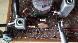
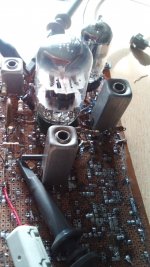
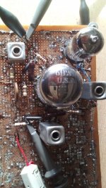
This morning I tryed the 6BW11 disimilar dual sharp cutoff pentode 12pin compactron tube with very good results. The high gain section (gm ~12mS) is the first stage and the lower gain (gm~8.5mS) the second. Once neutralized both stages indepently, no global oscilation was found, sincerely unknown if still persis some amount of re/de-generation. It is critical respect to oscillo tip placement, and the gain seems to be very high. Only crossing the generator cable to the input pin causes second stage to drive into limitation. Ebb is in the order of 140DCV, the cathode current of the first pentode is about 15mA with 220R as bias resistor, the second is about 8mA with 82R.
Seems that this layout is satisfactory. Decoupling from global Ebb is 470R common to screen and plate, and the former is live for RF in order to neutralization of Miller effect. Soonly, a schematic will be posted here.
Certainly, what is LNA in the above reply?.
Also I listen about pros and cons from the performance point of view, about ratio detector vs phase discriminator. Possibly I shall use a diode limiter at the second grid stage as depicted in the patents already added here.
Attachments


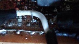
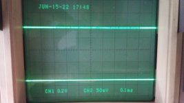
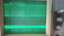
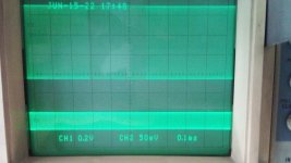
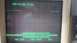
This are some pics of actual performing of the amp. The oscillogram is taken with a 10x tip not showing the read out, this fact. It is wired to the screen side of last IF transformer. Observe in the second pic a very loose coupling of the input pin to generator isolated cable. No idea of the real input level, I lack a calibrated RF gen.
Both stages are very simil regarding passive component values, excepting the cathode resistors already said, and screen cuasi-decoupling mica capacitor.
Both stages are very simil regarding passive component values, excepting the cathode resistors already said, and screen cuasi-decoupling mica capacitor.
Attachments

Thankyou dear.LNA stands for low-noise amplifier, jargon for the RF stage.
As you already have a working tunable oscillator for the receiver, set up a makeshift mixer, output connected to the IF. In an urban setting the local stations provide enough signal to see the result. If the IF gain is high enough, noise might be visible too.
In my case, discard the word low and let only noise amplifier 🙂)
LNA stands for low-noise amplifier, jargon for the RF stage.
Surely. During this week i shall try to design the limiter and detector stages. Prior to it, and as I have some more 6BW11, I shall try them to see if the stage is stable also with them.
Tonight I shall update the schematic and add it here.
Tonight I shall update the schematic and add it here.
Depending on the situation (like antenna on roof is forbidden) an LNA might be useful after all. With such a contraption you can build an antenna, small enough to be invisible from the street. Even for AM an LNA can be useful: it allows a small loop to be wideband. Tuned loops limit bandwidth below the 20 KHz used by a majority of stations. The LNA has to provide the gain the Q factor then no longer provides.
Recently, I tryed some other 6BW11 and the circuit continues performing as desired. Thus, I am satisfied with its behavior and has high chances to be the definitively topology. Tomorrow I shall try to add a limiter with two diodes inside 6JU8A in both formats: clamping to cathode bias and with automatic thereshold seted by the signal level. I refer to both patents depicted previouly (see my post #103).
I tried the limiter, and appear to do its job, more or less. Below, some pics. They are illustrating the first attemp to limit the second grid to ground, and to a cathode voltage. It will be best understand with the schematic, it resembles the idea from Chauvin @ post #103 but it isn't exactly like it. But wait for it some hours, please. From first to fourth, the lower trace is the input directly measured at the link input coupling means, and the upper is the output at the cuasi-decoupling capacitor of the second stage, screen grid live in order for neutralizing it. All pics with same oscilloscope sensitivity and @12MHz. If not perfect, limitation is easily seen as a ten-fold input only reflects a twice ouput signal in the 3rd and 4th pics when limiting appears to commence.
Attachments

Last edited:
Few minutes ago I tryed the second variant of a limiter, this one as a soft clamping to a RC network. Below are two pics in comparable conditions to the previous. Now, a 5-times increase in the signal level at the input reflects as a 2.5-3 times at the output. Rectified voltage at the clamping net increases from 100mV (contact potential) to over 2.2V when limiter action takes place. Coil adjust has changed slightly but tubes, passive elements excepting those belong to the clamping, are all the same; together with the instrumental used. EICO 368 generator a Kenwood CS5140 oscilloscope and GDM8040 bench multimeter.
Soonly both schematics, please be patient.
Soonly both schematics, please be patient.
Attachments

Finally, I made the desired schematics. The former is the corresponding to post #192 while the latter to #194.
Observe in the first, clamping to ground and to a twice cathode voltage, but grid returns to middle point, thus grid signal is symmetrically clamped to the single cathode bias. In the second, clamping level depends on signal strength. A 8.2K and a 10µF 63V film capacitor is the time constant (as a try only). 10nF plate is in parallel to proper RF bypass.
Observe in the first, clamping to ground and to a twice cathode voltage, but grid returns to middle point, thus grid signal is symmetrically clamped to the single cathode bias. In the second, clamping level depends on signal strength. A 8.2K and a 10µF 63V film capacitor is the time constant (as a try only). 10nF plate is in parallel to proper RF bypass.
Attachments
As all in the Earth changes, my project too.
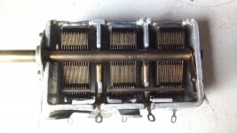
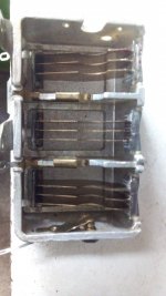
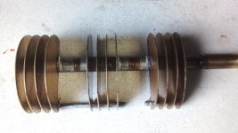
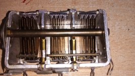
Yesterday l unespectedly could own a 3 section gang variable capacitor very similar to the used in my AM Tuner Project but with a couple of sheets less. It has about 450pF each section. So I dissasembled it and removed sheets to get a wonderful triple 25pF per section gang with brass plates. Thus, added to the difficulty for me for proper mechanical makes, l am almost sure to discard the original permeability tuning means that gave the tittle to the thread and migrate to a more common capacitance tuning.
Here pics of the before and the after.
The removing of plates from a variable condenser to get a smaller value unit has been used by ham radio for several decades here because of the availability of such stuff was difficult.
Attachments
Last edited:
For maximum selectivity from 2 RF circuits while maintaining good NF it could be useful to apply grounded grid input stage (EC86, 6S4PE etc.), minimally loaded BPF with high Q coils, followed by mixer.
Thank you. My idea is to maintain the cascode around a ECC88 or similar for the RF amplifier.
I am trying to acquire a couple of 6M11's. It has a double triode like a 12AT7 plus a 6EW6 pentode. One of the triodes as oscillator, the other as mixer and the pentode as first IF. Second and third will be the actual scheme with 6BW11 double pentode.
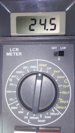
This the final value of the new gang with plates entirely closed.
I am trying to acquire a couple of 6M11's. It has a double triode like a 12AT7 plus a 6EW6 pentode. One of the triodes as oscillator, the other as mixer and the pentode as first IF. Second and third will be the actual scheme with 6BW11 double pentode.
This the final value of the new gang with plates entirely closed.
Attachments
Osvaldo, of course you do know that it is not the capacitance value with the plates fully in alone that counts, but the quotient between plates out and plates in that has to match your desired frequency range.
Btw, clever idea what you did with that tuning capacitor! How exactly did you remove the superflouos plates? Did you use a slim router bit in the Dremel?
Btw (2): Weeks ago I've removed a triple FM (plus double AM) tuning capacitor from an old so called receiver (radio + amp in one case) that suffered from a blown thick film power amp module. Sadly, one of the three parts appears to be fully shorted, and I don't recognize any reason at all for this severe issue, even not through a magnifying lens 😕.
Best regards!
- Home
- Source & Line
- Analogue Source
- A new FM tuner with Compactron Tubes