The connection for measuring Idss would look like this for a P channel transistor. Red and black leads in series with your meter set to mA.
Kevin,
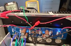
Thanks for the photo. Very helpful.
I'm back.
I put in new JFets N [Idss 7.03] and P [Idss 6.93]
Double checked all resistors.
PSU measures 24.30 +/- V [This suggests no current going to board]
Trim pots are set in middle range [12 turns from end]
Currently get no reading on P1 and -18.57 V on P2
Turning the pots doesn't get any change.
I suspect something is blocking current from entering the circuit board? Enough current is getting to board to fire up LED.
This is a new one for me.
Attachments
Last edited:
I cannot help, but I would like to commend your patience and effort. You are in my thoughts chiptech.
Can you take a measurement and tell me what the voltage is from pin 1 on an N channel MOSFET to pin 1 on a P channel MOSFET? If this looks like a TL431 problem, I have a couple (known good) I could throw in an envelope and send to you if there's a chance it might get you going.
I cannot help, but I would like to commend your patience and effort. You are in my thoughts chiptech.
Thanks for your support.
Sooner or later this will sort out.
Have you replaced the TL431?
Replaced the TL431
Same result
Pretty sure this is about some simple error I've made. I've checked all connections, etc.
Stumped
Would you mind double-checking the Mosfets without the washers just to verify if you installed the correct type in each spot?
Also, what is the voltage across C3 and C4? Does it change if you move P2 to each extremes?
Also, what is the voltage across C3 and C4? Does it change if you move P2 to each extremes?
Did you measure the voltage between the gate of an N-channel mosfet and
a P-channel mosfet as william2001 suggested?
Can you also measure the voltages across R8, R9 and P1?
a P-channel mosfet as william2001 suggested?
Can you also measure the voltages across R8, R9 and P1?
Would you mind double-checking the Mosfets without the washers just to verify if you installed the correct type in each spot?
Also, what is the voltage across C3 and C4? Does it change if you move P2 to each extremes?
Thanks. Will do tomorrow. Appreciate the patient assistance.
Did you measure the voltage between the gate of an N-channel mosfet and
a P-channel mosfet as william2001 suggested?
Can you also measure the voltages across R8, R9 and P1?
Dennis,
Will do this in the AM.
thanks,
Would you mind double-checking the Mosfets without the washers just to verify if you installed the correct type in each spot?
Also, what is the voltage across C3 and C4? Does it change if you move P2 to each extremes?
The Mosfets are in the correct positions.
How do i measure voltage across C3/C4?
Can you take a measurement and tell me what the voltage is from pin 1 on an N channel MOSFET to pin 1 on a P channel MOSFET? If this looks like a TL431 problem, I have a couple (known good) I could throw in an envelope and send to you if there's a chance it might get you going.
Pin 1 is the gate? If so, my reading is 0.005V
I have a supply of TL431 to run through. thanks
Did you measure the voltage between the gate of an N-channel mosfet and
a P-channel mosfet as william2001 suggested?
Can you also measure the voltages across R8, R9 and P1?
The Mosfet gate to gate measures 0.005V
R8 = -3.37V
R9 = -1.523V
Which resistor do I use to measure p1?
Thanks
Without the board in front of me I cant give other advise than to either look closely at the board, follow the PCB traces from P1 on each side, and once you end you at the next resistor/joint (following the traces from P1), attach your DMM to the joints/solder islands/resistor legs after P1 on either side/polarity, and measure the drop. Another way would be to dismount the board from the sink,and measure at the pins under P1, but… a bit more work…
Chip,
Measure Vref of the TL431. See attached image of board. One meter probe at D2 and other probe at R9. If the TL431 is functioning properly it should read 2.5Vdc.
To measure voltage at MOSFET gate, probe at Ground and probe at R10 for N channel and at R13 for P channel. Should read around 4.4Vdc or so.
Attachments

Sorry, I was thinking of the AJ board which has some pads which would make it easy.
In any case, your gate-to-gate measurement looks funny since it should be basically
the voltage across R8, R9 and P1. Please confirm you did measure across the gates
of mosfets of different polarities (for example, between Q3 and Q6).
If P1 is working then voltage across R9 and P1 should be about 2.5V.
Chip,
Measure Vref of the TL431. See attached image of board. One meter probe at D2 and other probe at R9. If the TL431 is functioning properly it should read 2.5Vdc.
To measure voltage at MOSFET gate, probe at Ground and probe at R10 for N channel and at R13 for P channel. Should read around 4.4Vdc or so.
D2/R9 reading = -2.127Vdc VS. 2.5Vdc
R10 = -15.3 Vdc vs. 4.4 Vdc
R13 = -20.79 Vdc vs. 4.4 Vdc
So Mosfet gate measures are bonkers.
- Home
- Amplifiers
- Pass Labs
- A guide to building the Pass F4 amplifier