I would think resistance between input positive and ground would be very high, so something is wrong.
I suppose there could be a path to ground through JFET gate to source if shorted or gate to drain if shorted, or through D3 or D4 if they are shorted, or through R2 if shorted.
I don't have a meter like Chip's so I don't know what the readout means. I would set the meter to measure Resistance rather than Continuity to be sure of the measurement.
Brainfart on my part, not unusual. Glad Ben stepped in! I have measured using the beep mode on a Fluke. If I am not mistaken, a beep means low resistance/good continuity. But I am not sure the R shown there is the actual R between the two, so excited to hear what the measurements are in resistance mode.
Last edited:
Chiptech,
Please confirm those measurements in resistance mode for both channels.
On post #2775
( https://www.diyaudio.com/forums/pas...ilding-pass-f4-amplifier-278.html#post6729623 ) you stated the same (negative) values for both,
yet commented they are very different.
Please confirm those measurements in resistance mode for both channels.
On post #2775
( https://www.diyaudio.com/forums/pas...ilding-pass-f4-amplifier-278.html#post6729623 ) you stated the same (negative) values for both,
yet commented they are very different.
Nice, this will lead to a solution I am sure. At least if the resistance mode shows something interesting.
Dennis: in post #2770 Chip posted readings of 7R3 for the left channel input, but prolly not in R mode. Anyways, divergence was around 32R.
Dennis: in post #2770 Chip posted readings of 7R3 for the left channel input, but prolly not in R mode. Anyways, divergence was around 32R.
My mistake.
I would still suggest a re-measurement in resistance mode since it's not clear what a
negative resistance value means.
Anyway, I'll bow out for now.
I would still suggest a re-measurement in resistance mode since it's not clear what a
negative resistance value means.
Anyway, I'll bow out for now.
There is something weird with the negative resistance. It indicates that there is current in the circuit. If the amp is off during the measurement there shouldn't be any current flow. Be sure any residual voltage in the supply caps is drained before making the measurements.
Are you sure that you haven't burn the input rca applying very hot airon for a long time?
I was on the road for past four days.
Today I checked continuity for left/right all RCA connects on input/output and got beeps across the board, including inside/outside of back panel.
I was out of town since Thursday. Today I went back and read thru all the posts since #2725.
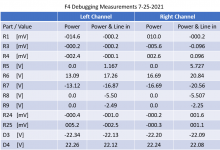
And I came up with new measurements for both channels, with power on and with power and signal in from Pre-amp [I've tested the Pre-amp many times and it delivers a signal to the left channel].
Looking at the numbers - the left R5 has a lower value than the right with the signal in on 1.167 vs. 5.727, but not sure what that might indicate?
Attachments
It indicates less current than through the right channel equivalent resistor. You need help from bigger Boyz, but as far as I can tell it might affect / be caused by what’s happening at the drain of Q2. An obvious and possibly unnescessary question is: sure that R5 is 1k and R22 750R? And is the voltage at the negative input of the PCB the same as at the negative rail of the PSU?
Good luck! Hope the AC is working…
Regards,
Andy
Good luck! Hope the AC is working…
Regards,
Andy
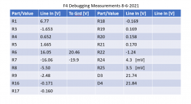
The left chan consistently has about 3 volts less than the right chan, at several measuring points. Strange… not only the R5 measurement is funny…
It indicates less current than through the right channel equivalent resistor. You need help from bigger Boyz, but as far as I can tell it might affect / be caused by what’s happening at the drain of Q2. An obvious and possibly unnescessary question is: sure that R5 is 1k and R22 750R? And is the voltage at the negative input of the PCB the same as at the negative rail of the PSU?
Good luck! Hope the AC is working…
Regards,
Andy
Andy,
The R5 and R22 are correct resistors.
The negative input is the same as the PSU 21.62 all around.
New system goes in tomorrow. Old system hasn't crapped out yet.....
Just determined the R9 is 8.5K instead of a 10K from the current F4 schematic.
Would that be causing my problem of part of my problem?
Would that be causing my problem of part of my problem?
That’s good news, Chiptech. It is always good to find possible explanations for errors!
I would replace R9 with the correct value. But I dunno it’s effect on your specific issue. What I would also do, is print the schematic from diyaudiostore, and measure every single resistor and mark the results on the printout. Then replace R9 and other parts that may be erroneous, and then try it again and see what happens 🙂
I would replace R9 with the correct value. But I dunno it’s effect on your specific issue. What I would also do, is print the schematic from diyaudiostore, and measure every single resistor and mark the results on the printout. Then replace R9 and other parts that may be erroneous, and then try it again and see what happens 🙂
Chip,
R9 might have been changed to 8.5k in order to be able to bias the Mosfets properly. It should not affect the front end so I see no need to change it if your Mosfets biased properly.
Looking at your voltages in your post #2788, I see that voltages with preamp connected and without the preamp connected are different. That is strange. I don't believe that should happen. Do you have another preamp or source that you can try?
Also when you provide voltages at resistors, please specify whether they are voltage drops across the resistor or at resistor referenced to ground. And if it is at a resistor referenced to ground, please show at which end of the resistor (mark on schematic). As shown, it is difficult to figure out what the voltages represent.
At this point it seems that one or both JFETs are not working.
I would like to bring up a previous comment of mine. You had bench tested the left channel and measured voltages that seemed correct, and then when you connected your preamp the JFETs seemed to stop working. You then replaced the JFETs, benched tested and measured correct voltages, connected your preamp, and again the JFETs seemed to stop working. So again, something about your preamp or your input wiring may be causing this.
Ben,
Just checked using the Starving Student headphone amp, same result, no sound from left channel.
I can go back and get more specific on my measurements.
I also think it has something to do with my input wiring. Perhaps I should swap those wires out for new ones.
First I will provide better defined data.
It's a .0033uf (3300pF) cap that must be x1 (or x2) rated for across the line use.
Here's a link to an appropriate part-
WKP332MCPEJ0KR Vishay / Roederstein | Mouser
Can someone link a substitute to the above? Its holding up my parts order. I've never worked with a cap of this spec before, so I'd rather get help than watch one blow up across 120VAC. 😀
Well I have sound - softly
I replaced the in and out wires and replaced the JFets.
Biased again.
And plugged it into my system.
I get a very low volume from the left channel, which is better than no volume.
I've attached new measurements, but as puzzled as ever.
I replaced the in and out wires and replaced the JFets.
Biased again.
And plugged it into my system.
I get a very low volume from the left channel, which is better than no volume.
I've attached new measurements, but as puzzled as ever.
Attachments
- Home
- Amplifiers
- Pass Labs
- A guide to building the Pass F4 amplifier