Yea, the JFETs he has now should be above 6. but Chip where those numbers given by the seller or measured by you? As Dennis pointed out your method might not be 100% accurate for this purpose. Given the IDSS is that low, I would consider asking for a reimbursement. You might not be able to tell the difference between 4 and 5 mA, but it means they don’t bias to spec, and if the IDSS is too low, you won’t be able to manipulate it up through resistor changes either. But as you pointed out the fets prolly aren’t the main cause of all of this.
Still excited to see what the solution to your issues turns out to be! Or is it all working now?
I haven't tested it yet. WE learned today our HVAC is likely to give out at any moment and its only 6 years old. Parts are out 6-8 weeks. Been rather warm down here in southern AZ. So a little distracted today.
I don't know whether the difference is critical. Since it is working, play some music and decide if it sounds good to you.
That's disappointing.
1. Check bias of Mosfets
2. Check voltage across JFET source resistors R3 and R4
3. Check DC offset at speaker output
4. Check wires from RCA jack to board and from speaker connectors to board
5. Try switching input signal Left to amplifier Right input and input signal Right to amplifier Left input
1. Check bias of Mosfets
2. Check voltage across JFET source resistors R3 and R4
3. Check DC offset at speaker output
4. Check wires from RCA jack to board and from speaker connectors to board
5. Try switching input signal Left to amplifier Right input and input signal Right to amplifier Left input
4. Check wires from RCA jack to board and from speaker connectors to board
5. Try switching input signal Left to amplifier Right input and input signal Right to amplifier Left input
👍🏻
That's disappointing.
1. Check bias of Mosfets
2. Check voltage across JFET source resistors R3 and R4
3. Check DC offset at speaker output
4. Check wires from RCA jack to board and from speaker connectors to board
5. Try switching input signal Left to amplifier Right input and input signal Right to amplifier Left input
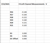
7/22 measurements
see attached chart
Also checked wires from RCA jack to board and speaker connections to board. Look good.
switched input signal left to right, no change.
Still feels like some simple issue, but I can't find it.
Might be time for a new left channel.
Attachments
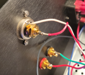
A quicker test than rewiring might be to do a DMM beep test on the signal and return from your RCA input on the left chan. That can reveal a broken wire. Also, check resistance between RCA positive and gnd. If zero between signal and return solder joint at the socket, you prolly have a short somewhere. Pics of the input sockets might prove helpful. Good luck!
Edit: sorry, did not see your last. Too bad 🙁 Sure there isn’t a short at the input socket? Probably a dumb question, but…
Edit: sorry, did not see your last. Too bad 🙁 Sure there isn’t a short at the input socket? Probably a dumb question, but…
Last edited:
That's strange. Your R3 and R4 numbers have changed.
Can you please disconnect the the amp from the input source, take it back to the bench,
and measure the voltages across R3 and R4 again, both for the left and right channel?
Can you please disconnect the the amp from the input source, take it back to the bench,
and measure the voltages across R3 and R4 again, both for the left and right channel?
Both times (old JFETs and new JFETS) the R3 and R4 voltage drops were good on the bench, indicating functioning JFETS, but once a source/preamp was connected at the input the voltages across R3 and R4 disappeared.
So the source/preamp somehow caused it? Or is there some issue with the amp that only shows up when a source/preamp is connected to the input? Check preamp output for DC?
Puzzled.
So the source/preamp somehow caused it? Or is there some issue with the amp that only shows up when a source/preamp is connected to the input? Check preamp output for DC?
Puzzled.
Nice conclusion. You prolly did this, but have you tried swapping the input wires from the preamp from right to left? Think I read you did that before…
Ben, 7R3, could that be the CL-60 he is seing? And if so, might there be an erroneous connection to gnd on the left chan, perhaps somewhere else than the input section?
Hmmm. Suddenly thinking about a mild mild conductance between one of the output fets and chassis as a possible option.
Should he not be seeing more than 7R3 between signal and signal return sockets? That’s the kind of R I’d expect between chassis and audio gnd normally.
Hmmm. Suddenly thinking about a mild mild conductance between one of the output fets and chassis as a possible option.
Should he not be seeing more than 7R3 between signal and signal return sockets? That’s the kind of R I’d expect between chassis and audio gnd normally.
Last edited:
Same on right?
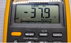
Right channel:
RCA input -37.9
RCA output -37.9
Quite different measures vs. left channel
Checking both RCA input/RCA output for left channel both beep and I get a -7.3 ohms reading.
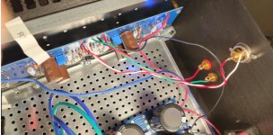
see photos
Are you sure that you haven't burn the input rca applying very hot airon for a long time?
Right channel:
RCA input -37.9
RCA output -37.9
Quite different measures vs. left channel
Sorry, but please confirm you read in Ohms and not KiloOhms?
Are you sure that you haven't burn the input rca applying very hot airon for a long time?
To check this you could for example cut both signal and return at the PCB end, isolate/leave hanging in the air, whatever works, and then measure resistance between the two input solder pads. R should be infite (many, many K). But if I remember correctly, you have allready tried swapping wires from side to side, so that excludes the input RCA, no?
Last edited:
Sorry, but please confirm you read in Ohms and not KiloOhms?
Ohms
see photo
Attachments
- Home
- Amplifiers
- Pass Labs
- A guide to building the Pass F4 amplifier