Chip, please also measure the voltages across R6, R7 and R8, and please confirm the part values you used there.
There is not enough current (<0.17mA) through the TL431 for it to be regulating.
The new part kindly supplied by william2001 will address the regulation,
but I think there is a problem elsewhere that is causing the low current
through R6 feeding the TL431.
Can you please check the voltages across R3, R4, R5 and R22 and confirm
the values of those resistors.
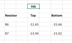
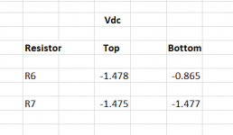
Then with your voltmeter ground probe on the ground of the circuit, please
measure the voltages at:
-R6 (both ends)
-R7 (both ends)
Also, please confirm your rail voltages.
The new part kindly supplied by william2001 will address the regulation,
but I think there is a problem elsewhere that is causing the low current
through R6 feeding the TL431.
Can you please check the voltages across R3, R4, R5 and R22 and confirm
the values of those resistors.
Then with your voltmeter ground probe on the ground of the circuit, please
measure the voltages at:
-R6 (both ends)
-R7 (both ends)
Also, please confirm your rail voltages.
Last edited:
Looks frightingly like dead JFETs to me. But didn’t you just replace them? If not dead, they are indeed sleeping for some reason. It will be interesting to see what the Greedy Boyz think.
Last edited:
An observation.. we want that input jack (R2) shorted to ground for any setup and troubleshooting of the amplifier. Nothing connected to the outside world and not floating, just a hard short. We would want to see maybe ~100 mV or something ACROSS R3 and R4 (if those are 22 ohm resistors as shown in post #1) accordingly so a reading of zero is concerning.
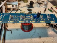
Can you please check that you have the correct jfets in the Q1 and Q2 locations
(Q1 = 2sk170/lsk170, Q2=2sj74/LSJ74)? Remove any shrink wrap/zip tie
and gently bend back the jfets if necessary.
(Q1 = 2sk170/lsk170, Q2=2sj74/LSJ74)? Remove any shrink wrap/zip tie
and gently bend back the jfets if necessary.
Another crack at this.
Please check the voltages across R3 and R4 and confirm their
resistor values. You may want to use your meter's mV scale for this measurement.
Check voltages across R22, R6, R7, R5, R8, R9 and confirm their resistor values.
Please include units with all your values.
Some of your previous measurements are difficult to reconcile assuming the
standard part values. (For example, voltage across R22(750 ohm) )
Dennis,
I confirmed all the resistors are in the correct slots.
However for R22. something looks off. It's the right value [750 0hm], but testing it on the board I get very weird reading of ~12.78K.
So I think I will wait for the new TL341 and replace R22 with a new 750 ohm resistor at the same time.
For my understanding what do you mean "include units with all your values,"?
Thanks
Chip, I meant that, for example, when you write a voltage value that you
indicate the unit used (V, mV, etc).
Please check back in after you've changed out those parts.
indicate the unit used (V, mV, etc).
Please check back in after you've changed out those parts.
Did you lift one leg of R22 to test it? You can’t just place a meter across it and read it’s resistance, there is a lot in parallel with it.
Lift one leg, measure, replace only if not in the ballpark.
Lift one leg, measure, replace only if not in the ballpark.
Is that true for all DMM’s? During troubleshooting I once checked all my WLS resistors in circuit, and they measured correctly, if I remember correctly that is 🙂 Used a Fluke.
That said, I think Chip confirmed 750R in the R22 position once when I asked him. But was that after a measurement or based on the color coding?
That said, I think Chip confirmed 750R in the R22 position once when I asked him. But was that after a measurement or based on the color coding?
Last edited:
I once checked all my WLS resistors in circuit, and they measured correctly, if I remember correctly that is 🙂
Well, that's a fluke. 🙂 It really depends, as Jim mentioned, on what kind of
equivalent resistance is seen in parallel with a resistor in circuit.
If I'm understanding things correctly, Chip measured ~12K across R22,
which is substantially higher than 750R. And I expect any parallel resistance
should make the measured value lower, not higher. So I believe R22 has
gone bad.

C3 and C4 are decoupling caps, but C1 and C2 are coupling caps.
I'd guess the RC network of R5/C3 needs to be large enough to at least filter out 50/60hz junk, while C1 with whatever resistance makes up its network (R5 + R7?) needs to be large enough to pass your bass frequencies.
If I've got that right, then as designed they're no where near the frequencies we care about, so yeah, the values are not critical (within a reasonable order of magnitude).
- Home
- Amplifiers
- Pass Labs
- A guide to building the Pass F4 amplifier