C3 and C4 are decoupling caps, but C1 and C2 are coupling caps.
I'd guess the RC network of R5/C3 needs to be large enough to at least filter out 50/60hz junk, while C1 with whatever resistance makes up its network (R5 + R7?) needs to be large enough to pass your bass frequencies.
If I've got that right, then as designed they're no where near the frequencies we care about, so yeah, the values are not critical (within a reasonable order of magnitude).
Thanks Jeff, i hope that we will have more answers now😉
Now for some good news, for a change
Yesterday I replaced R22, R6 and the TL341 [NCP431ACLPRAGOSCT-ND], graciously provided by William2001 .
I biased the left channel to .171 Vdc zeroed out offset.
After running a combined 15 hours - everything works and sounds great!
Both channels are running around 50C.
Being gun shy, I will start to believe things are sorted after more hours on the clock.
Thanks to all in this forum who had the patience to help me over the last 3 months. I could not have done it without all the patient assistance.
So thanks again,
Chip

That's great to hear Chip. Hope those gremlins stay away for good. F4 is a good amplifier, one of my favorites for sure paired with an appropriate linestage with enough gain / swing.
@ Chip - true testament to perseverance, i likely would have thrown the towel in a looooong time ago. congrats
Congratulations! It has been a learning experience to follow your progress. Thank you, and good job, chiptech!! 
Chiptech!
I have been following as well! The news is absolutely fantastic, so thrilling for you and such a learning experience even though you have a few Pass designs under your belt!
Let us know what you think…
Best,
Anand.
I have been following as well! The news is absolutely fantastic, so thrilling for you and such a learning experience even though you have a few Pass designs under your belt!
Let us know what you think…
Best,
Anand.
Pass DIY Addict
Joined 2000
Paid Member
Wow! That was a long journey - congrats to you on a working amp! We’ve all been there with one build or another. It’s incredibly frustrating along the way, but soooooo very satisfying when you solve the problem! Time to enjoy now!
Chiptech, fantastic to hear you sorted out all the challenges. I have also been following your journey.
Kudos for your determination!
Enjoy your new amp! 🙂
Kudos for your determination!
Enjoy your new amp! 🙂
I had bolted an F4 channel to an unused heat sink and powered it with a lab supply...the idea being that as you guys called out measurements I would check them on my own F4...helping me to understand the circuit a bit better. Now that Chip's issue has been solved (hooray!) I'm left to my own experiments. The first being to pump up the supply voltage incrementally until I hit 30V, but that didn't seem to translate into much more usable wattage on the output.
Anyway, I'm sure you guys are getting your voltage readings off a sim of the F4 when calling them out to Chip. I'm a novice using LTSpice at best. Would it be to forward to ask someone to share their simulation? I know there's a lot of work that goes in those things.
Anyway, I'm sure you guys are getting your voltage readings off a sim of the F4 when calling them out to Chip. I'm a novice using LTSpice at best. Would it be to forward to ask someone to share their simulation? I know there's a lot of work that goes in those things.
Mosfets ok?
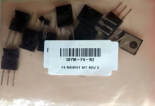
I ordered an F4 transistor kit from the DIY audio store.
Surprisingly, the contents were not packaged in bubble wrap or a static-safe envelope. As a result, they don't appear to have weathered transit very well.
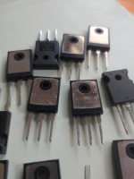
Some pins are bent; and the silvered surface of several of the mosfets seem to have been scratched by the pins of the others.
Similarly, the two tiny TL-431s were loose - not taped like shown on the image on the store site. Their pins are also bent.
Can folks with experience tell whether these transistors are good for use? Or should I ask for replacements? I'm past the store's 30 day return/exchange policy so I can only hope they'll help.
Any suggestions?
I ordered an F4 transistor kit from the DIY audio store.
Surprisingly, the contents were not packaged in bubble wrap or a static-safe envelope. As a result, they don't appear to have weathered transit very well.
Some pins are bent; and the silvered surface of several of the mosfets seem to have been scratched by the pins of the others.
Similarly, the two tiny TL-431s were loose - not taped like shown on the image on the store site. Their pins are also bent.
Can folks with experience tell whether these transistors are good for use? Or should I ask for replacements? I'm past the store's 30 day return/exchange policy so I can only hope they'll help.
Any suggestions?
Attachments
I can only speak for myself, but mine were shipped the same way in several different orders. And work just fine 🙂
Mark Johnson, I think it was he who wrote it, says it is a good idea to sand the surface with very fine paper anyways in general. I guess iot ensure even contact with the pads. Either way, they look OK to me.
That said, some of the ones I got weren’t as tightly matched as expected. Is the reason damaged surfaces during transport and therefore uneven pad contact? I must say I haven’t thought about it, but I guess everything is possible. But I don’t think so.
Wrt returns, I have tried that once. But you might have more luck than me 🙂
Cheers.
Andy
Last edited:
Same here. Your photos show the way my parts arrived.
And I've ordered a lot of parts.
But not because any of them were bad.
And I've ordered a lot of parts.
But not because any of them were bad.
- Home
- Amplifiers
- Pass Labs
- A guide to building the Pass F4 amplifier