Using my phone to avoid the phone game. 😆
@ggetzoff : yes, voltage is at the boards. V+ and V-.
Zen:
post your reference schmtc (or link to)
See attached. 2011 revision. All resistor values as indicated.
bulb tester only for initial - no biased - state
remove bulb tester, or - as soon you start increasing bias, amp is going in voltage starving
Thank you.
you'll need to alter few resistors , nothing more
So perhaps the combo of TL431 and R9 / R8 values causing it not to breathe past the jfet stage? I don't quite understand what the TL 431 does in the circuit. I do have others (OnSemi NCP431ACLPRA) I purchased.
There's a 16V drop across R6 (10k).
Last edited:
can't see nuttin at that schm, too small - can't see nomenclature even if I can see most important values
increase 22K - upper TL431 resistor - to 33K
set 5K trimpot to max value prior to powering up
be constructive how to check that max value with ohmmeter
or leave 22K as is, replace lower TL431 10K resistor to 5K1
increase 22K - upper TL431 resistor - to 33K
set 5K trimpot to max value prior to powering up
be constructive how to check that max value with ohmmeter
or leave 22K as is, replace lower TL431 10K resistor to 5K1
Thanks, I'll rummage around the old resistor box and see what I can dig up.
Yes, will set 5k Trim to max measuring across it and R9.
Yes, will set 5k Trim to max measuring across it and R9.
As both channels are (mis)behaving the same way, I'm going to focus on one.
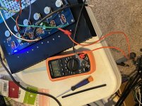
I replaced R9 (originally 10k) with 5k1. Started with P1 trimmer to max. Rails at 23v, reduced P1 full way, and never budged from 0.00 voltage drop across the Source resistors (used R20, r21). Also, no voltage drop across gate resistors (R10-R12). They show approximately 1.3V
Because I have them, replaced the TL431 with the OnSemis I had ordered, triple-checking the pin-outs as per schematic.
Reference and readable schematic I'm following is attached.
Attachments
For my education, to understand that portion of the circuit, I think...
R8 and R9+P1 form a voltage divider, sending a positive voltage into the TL431,.
Which from what I can understand is acting as a zener, setting a specific voltage from the TL431?
But this in turn is talking to the D1, D2 zener pair. And I'm lost as to the purpose.
Understanding that this little network is setting a bias for the mosfets on the Out line between the N and P sides.
Nope, I don't get it yet.


There should not be much voltage drop across the gate resistor since the DC gate current is negligible. However there should a bit over -4V from gate to ground in order to open up the mosfet.
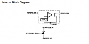
It may be that your TL431 is not functioning properly. A check of that would be to measure the voltage between Ref and Anode, which should be 2.5V if it is working.
It may be that your TL431 is not functioning properly. A check of that would be to measure the voltage between Ref and Anode, which should be 2.5V if it is working.
Measure between the Ref pin and the Anode pin of the TL431. You should see the Ref voltage of 2.5 volts. Divide 2.5 volts by the resistance, I=V/R, between Ref and Anode (this would include the potentiometer.) This current then flows thru R8 developing a voltage. Add 2.5 ref voltage and the voltage across R8. This is your bias voltage.For my education, to understand that portion of the circuit, I think...
R8 and R9+P1 form a voltage divider, sending a positive voltage into the TL431,.
Which from what I can understand is acting as a zener, setting a specific voltage from the TL431?
But this in turn is talking to the D1, D2 zener pair. And I'm lost as to the purpose.
Understanding that this little network is setting a bias for the mosfets on the Out line between the N and P sides.
Nope, I don't get it yet.
With the original values and the potentiometer at mid point. 2.5/12.5K=0.2ma. 0.2ma x 22.1K=4.42 volts. 2.5 Ref voltage plus 4.42 volts =6.92 volts
With the pot at zero, bias voltage is 8 volts
With pot at max 5K, bias voltage is 6.18 volts
Vout=(1+R8/(R9+P1))Vref
D1 and D2 provide over voltage protection
Hope that helps you get started
Attachments
I suppose 22R won't do the work of 22.1k in R8, now will it? Stupid clerical error identified.
I have a 20k for R8 in my box.
With @BDP 's formula above and the 5k1 in R9 position, that will give me:
P1 pot at zero, bias of 12.5V
P1 pot at max 5k, bias of 7.5v
If I put the 10k back in R9, I'll get close to BDPs range above.
What's the better option for R9 given R8 of 20k not 22.1k?
I'll put R8 20k in on the other channel that still has 10kR9 and see if I can bring it up.


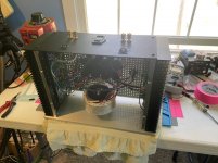
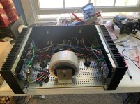
Got it fully assembled and biased yesterday. Boring, long conference calls can be a blessing if you build your amps in the home office.
When biased, the DC offset trim (P2) let me adjust to .1mV and just sat there, rock steady.
As advertised, what a revealing amplifier of whatever is driving it. I played with a VTL tube pre and the B1 Korg. The VTL was just liquid and lush and detailed but anemic in the bass, and the B1K brought back that bass foundation with a trade-off in detail. But I can also play with the B1K's character to pull out a little more detail. It is an odd experience to turn up a volume knob to 2:00 or even beyond when coming from a lifetime of 11:00 is plenty. I've got a few other pre-amps around I'll give some time with it.
At that point, I just sat back and enjoyed the music.
Attachments

Congrats!
Looking good - and the F4 is just an instantly rewarding amp to listen to 👍
Biggest challenge is then finding a worthy and gain capable PreAmp 😊
Looking good - and the F4 is just an instantly rewarding amp to listen to 👍
Biggest challenge is then finding a worthy and gain capable PreAmp 😊
Which version of the 01A? Do you have a reference schematic you can link to?So if I understand correctly, there is no way to get more power from F4 with single ended inputs, because monoblock configuration will just give me more current capabilities right?
I'm listening to F4 paired with Ale Moglia's 01A SIC biased pre for a few days now and I'm totally delighted.
This combination has all the pros of DHT and all the hard work is perfectly done by F4.
What will be best option to get more power from this setup? Some kind slightly step-up balancing transformer?
Right now I'm totally satisfied by spl I get from my Alpairs 7.3. But I'm about to move to bigger place in near future, so more power might be needed.
I too have a 01A preamp. Mine is the Gen 2 version using Ale's gyrator boards and Rod Coleman filament supply boards. PSU is with AZ1 tube rectifier, 2 chassis via umbilical cord.
Very nice sounding preamp with an F4 but IMO not the best match especially if you seek mid-high SPL as it is easy to discern that it needs help pushing the F4. For all tube system, it is hard to beat at the cost to build one.
Also, very difficult to source a quiet pair of 01A (and its variants 201, 301). If you build this preamp, buy tubes from retailer sites not from ebay as you will likely be disappointed.
In my case, so far, the BA3-FE preamp is the best match for my F4.
- Home
- Amplifiers
- Pass Labs
- A guide to building the Pass F4 amplifier