can you grasp this?
I know it demands some work ......
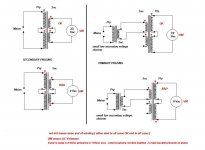
on the other hand ....... I presume that's dual primary Donut , so check with continuity test am I on right track :
Yellow One and Red One are one Primary
Yellow Two and Red Two are next Primary
if yes , for UK mains ( aroundish 230Vac?) , connect Yellow one to Phase , then together Red One and Yelow Two ( insulate that connection) ,then Red Two to Neutral
if you're using regular fuse (750VA/230Vac = approx 3A15T) , nothing catastrophic can't happen , except maybe some heart palpitation 🙂
well , all this counting that your're speaking about primary colors , while secondaries are ignored this time
just in case - secondaries are always having much fatter wire , while primaries and shield are having skinnier
I know it demands some work ......
on the other hand ....... I presume that's dual primary Donut , so check with continuity test am I on right track :
Yellow One and Red One are one Primary
Yellow Two and Red Two are next Primary
if yes , for UK mains ( aroundish 230Vac?) , connect Yellow one to Phase , then together Red One and Yelow Two ( insulate that connection) ,then Red Two to Neutral
if you're using regular fuse (750VA/230Vac = approx 3A15T) , nothing catastrophic can't happen , except maybe some heart palpitation 🙂
well , all this counting that your're speaking about primary colors , while secondaries are ignored this time
just in case - secondaries are always having much fatter wire , while primaries and shield are having skinnier
Attachments
Would somebody be kind enough to clarify whether the TL-431ACLP is a suitable part to use in the F4 build please?
It seems there are more versions of the TL-431 than there are fish in the sea! Mouser don’t have a “regular TL431” as ZM suggests we use (in F4 power amp thread -post 4399), they all have a string of letters after the 431 and the data sheet doesn’t make it clear what those letters mean.
Dennis Hui said (post 4400) “The F4 schematics, with TL431 shows an adjustment range of around 7 to 9.4V”
The 431ACLP datasheet says “The output voltage can be set to any value between Vref (approximately 2.5 V) and 36 V, with two external resistors”, so I assume (always a dangerous thing) that the TL-431ACLP will work just fine in the F4 circuit with the standard resistors for R8 and R9. Is that a correct assumption? Thanks.
it'll work, as charm
problem never was in suffix , it always was either in bad part or short circ between headphones

problem never was in suffix , it always was either in bad part or short circ between headphones
I did a little tester called "PhaseDots" a few years ago. You hook it up to a transformer and it helps you decide which end of a winding is the in-phase ("dotted") end.
You could slap it together on a solderless breadboard / Proto-Board in 90 minutes.
You could slap it together on a solderless breadboard / Proto-Board in 90 minutes.
TL431A is 1% accuracy, TL431B is 0.5% accuracy, and TL431(blank) is 2% accuracy. The other letter suffixes denote package types.
TL431A is fine, more accurate than TL431.
TL431A is fine, more accurate than TL431.
With 37 thousand in stock, I’d go with this one as the ‘jellybean’ TL431 🙂
TL431AIZ-AP STMicroelectronics | Mouser
TL431AIZ-AP STMicroelectronics | Mouser
I now have one yellow which has continuity to the red wire in the same block.
This time the LEDs flashed on then it blew the fuses.
Is there anything else I can look into?
This time the LEDs flashed on then it blew the fuses.
Is there anything else I can look into?
First, disconnect the amplifier boards from the PSU. You don't need to have them attached until the PSU is sorted and working. 🙂
Which secondary leads are mates? Each secondary is a single piece of wire looped around the core, that wire has a beginning lead and an end lead. Continuity test will show which is one end and which is the other.
Check your PM
Which secondary leads are mates? Each secondary is a single piece of wire looped around the core, that wire has a beginning lead and an end lead. Continuity test will show which is one end and which is the other.
Check your PM
@Belmondo - Follow the advice provided. I made the error of ordering a close, but not quite part. TLV431ILPR... This wonderful community helped me realize and correct the error of my ways after my MOSFETs wouldn't kick in. Low Voltage version ... nope... nope... nope. Oops 😀
Thanks again for all the advice, much appreciated, especially by ItsAllInMyHead. I did read about you prefix problem which is why I started paying attention to the types of TL-431. 6L6’s recommended part is now in my BOM
I’m now at the last hurdle with my BOM. Trim-pots. Bourns has different pin configuration - straight and offset - all have 3 pins but there are 4 holes on the pcb for the trim pots. Little things like this completely throw a beginner!
Are there 4 holes so I can use trim pots with either the 3 pins in-line or those with the pins off-set? I don’t want to buy the wrong ones as they are relatively expensive and then there’s the carriage cost on top for a re-order if I'm wrong! I’m looking to buy this: 3296W-1-502LF Bourns | Mouser Российская Федерация
and the 500 ohm version. Thanks again for your help. I’d be lost and pulling out what’s left of my hair without it!
@belmondo - if you're so inclined. If I had it to do over again, I'd have put in the pots with the adjustment on the side. I can't remember if the F4 boards have both in-line and Y configuration, but something like this makes it so much easier to adjust the bias and offset. I couldn't find the exact part I was looking for, but someone with better Mouser-Fu skills may be able to jump in with the exact part number for both pots.

boyz
use tweezers , if pins are different than holes line-up
I would do it even for medical instruments, I did it zillion times repairing money-making gadgets ......
🙂
use tweezers , if pins are different than holes line-up
I would do it even for medical instruments, I did it zillion times repairing money-making gadgets ......
🙂
@ItsAllInMyHead: I've found a top adjusting trim pot on Mouser(Bourns call it vertical adjusting) and the Y-version is available so that's what I'll go for as long as the values are available.
Thanks again.
Thanks again.
- Home
- Amplifiers
- Pass Labs
- A guide to building the Pass F4 amplifier