Photobucket appears to be down, or similar. Horrible website, I wish I never used them back in the day...
Resistors - which one?
Hi friends!
I'm ordering the parts for my try on a F4...
For the R16 - R21 (.47R 3W), classy Metal-Film-Resistors are the way to go I presume?
(Mouser has them metal-film or metal-oxide (and even wire wound)...)
For the other Resistors, I'm tempted to go with 1/2 W instead of 1/4 W, but not every resistor is available. Is a mix between various power ratings a problem / should I stick to the BOM strictly?
Thank youu!
david
MOX or MF ,3W
other are good even 1/4W , but be aware of fact that most MF of 0207 size today are in fact 600mW
not that anything is wrong with that
other are good even 1/4W , but be aware of fact that most MF of 0207 size today are in fact 600mW
not that anything is wrong with that
Avoid wirewound for the 3W, other 2 depending on budget, MOX are usually used. No problem mixing 0,25 & 0,5W, mostly derating for meeting specs. Watch the sizes of resistors vs. PCB footprint.
@myleftear -
Hi. The 3W Panasonic Metal Oxide parts seem to be the norm, but those are either at end of life or obsolete - I'm not sure which. You can still get them if you want, but any 3W metal film should work well. The KOA Speer Metal oxide sold through Mouser seems to be a common substitute among some builders too. I'm sure someone will chime in if I'm incorrect.
re: power rating for resistors - I just get piles of 1/2W or 0.6W parts in the common values. I believe Mark Johnson or 6L6 had provided that guidance when I had the same question. I haven't found a situation yet where the higher-rated part won't fit on the boards, and they're literally only pennies more.
Enjoy! I love my F4.
Edited to add - Holy Moly people are fast. Two replies while I was typing.
Thanks to all!
That's what makes this place so cool. Next to the smell of solder late at night 🙂
MOX or MF ,3W
not that anything is wrong with that
Avoid wirewound
3W Panasonic Metal Oxide
That's what makes this place so cool. Next to the smell of solder late at night 🙂


Heatsinkd (not again! 😛 )
Sorry, again about the heatsinks, and good morning to all anyway!
I'm studying 6L6's build guideover and over...
The transistors are mounted at around the lower quarter of the heatsink. Wouldn't it be much more effective if they'd be centered? (Isn't the upper 1/4 wasted?)
(for a working build-guide with the pics, engage your warp-engines to 9.9 and rotate counterclockwise around earth until you reach this point here — thanks @YeffYoung !)
I virtually divide the heat in 3 equal parts horizontally and drill/tap the mounting holes for the transistors on the lower horizontal line.
Others may do it differently, remember heat goes up.....
EDIT: You can model your heatsink and play around with placement of the outputs on that said heatsink and see if you like the results. As per the results hereunder you will see that I omitted some important values, my goal at that time was uniform heat spread more than very excat temp. calc...
Attachments
-
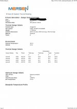 Temp Radia, ext de 35mm du bord_ bas du transistors a 75mm du fond(2)1.jpg181.8 KB · Views: 323
 -
 Temp Radia, ext de 35mm du bord_ bas du transistors a 75mm du fond(2)2.jpg59.6 KB · Views: 291
 -
 Temp Radia, ext. 40mm du bord_bas du transisotr a 75mm du fond1.jpg181.5 KB · Views: 297
 -
 Temp Radia, ext. 40mm du bord_bas du transisotr a 75mm du fond2.jpg59.9 KB · Views: 294
Last edited:
Sorry, again about the heatsinks, and good morning to all anyway!
I'm studying 6L6's build guideover and over...
The transistors are mounted at around the lower quarter of the heatsink. Wouldn't it be much more effective if they'd be centered? (Isn't the upper 1/4 wasted?)
(for a working build-guide with the pics, engage your warp-engines to 9.9 and rotate counterclockwise around earth until you reach this point here — thanks @YeffYoung !)
Probably because heat rises.
Probably because heat rises.
Sorry for getting nitpicky, but I understand it differently: Isn't it so that warm air (relative to the air around) is rises, not "heat"? The heat from the Mosfets is transferred into the heatsink, which it distributes (warms up). I imagine it more like a blotting paper, concentrically soaking up fluid ...
The air floating around the heat source takes up the energy and begins to rise due to the thermal expansion. (Thus, wouldn't it be that the upper region of the heatsink becomes a little less effective because the air already got warmer?)
but anyway: 😕 it's complicated.
david
Last edited:
That is a big heat transfer question but the difference is small. It could be easily measured if proper protocol is followed. I would theorize that between center and the bottom 1/4 of the smooth side of the heatsinks with the fins aligned vertically will result in the highest heat dissipation.
The best place to connect pin 1 of an xlr is directly to the chassis at the point of entry. This way the ground wire won't become a broadcasting antennae inside of the chassis as some long resistive impedance laden wire on its way to ground. A single point of connection between power ground and the chassis is nice for safety reasons, but this time through about 10 ohms resistance or possibly better a cl60 thermistor to help reduce ground hum and noise.
Sorry for getting nitpicky, but I understand it differently: Isn't it so that warm air (relative to the air around) is rises, not "heat"? The heat from the Mosfets is transferred into the heatsink, which it distributes (warms up). I imagine it more like a blotting paper, concentrically soaking up fluid ...
The air floating around the heat source takes up the energy and begins to rise due to the thermal expansion. (Thus, wouldn't it be that the upper region of the heatsink becomes a little less effective because the air already got warmer?)
but anyway: 😕 it's complicated.
david
It is a very complicated dynamic: as the air goes up, the flow changes from laminar to turbulent based on Rayleigh’s number. The exact calculation requires solving partial differential equations, but best to rely on manufacturers empirical measurement data
Take it with a pinch of salt, just a rusty mechanical engineer is speaking 🙂
- Home
- Amplifiers
- Pass Labs
- A guide to building the Pass F4 amplifier