I would not use an inductor or extremely large capacitors, both will cause problems. You can make a pi filter and replace the inductor with a ferrite bead. Remember ceramic capacitors are you best bet to filter out HF ripples and you don't need a lot either. Make sure that you use one that rated for twice your normal operating voltage.
Check out http://www.ti.com/lit/an/slva549/slva549.pdf for more information regarding filtering.
http://carvermk2.com/Docs/Carver Magnetic Field Whitepaper.pdf explains why one needs so much capacitance with an unregulated transformer.
https://www.calex.com/pdf/3power_impedance.pdf talks about what can happen if you use too much capacitance
I have even added LDO to help reduce ripple in some power supply designs. However that shouldn't be needed.
Last edited:
Hmm, my bad, that last article isn’t about using too much capacitance. It’s about impedance matching which is something I haven’t tried. Using too many caps can prevent the smps from starting up.
Alright, but it seems like the cap/ferrite accomplishes the same thing according to the TI paper. I guess if it is possible to bring ripple down to a few mV, whether that ripple is at the mains or a smps frequency isn’t such a big issue... or what am I missing?
Correct, their HF noise is not audible and most modern ones won’t be heard. If they are, then there are ways to filter that noise out. It’s just not the same as you would do with a large low frequency (mains) transformer and there are many different topoglies for smps. I never tested my supply without the three additional caps. Even with the caps the total cost was less than the traditional power supply setup. Another benifit is that run cooler and weight less.
Does anyone hear a hum when their F4 isn’t playing music? Mine does not and I had forgetten about that quirk some amps have until I was doing a sound comparison with a B&K ST-260 (which does have a hum when no audio is being played).
Hi all, really glad to see this thread is still active after all these years. I'm going to embark on a build in order to use the f4 as a booster amp for my Coincident 300b monoblocks (controlling the bass units of my Coincident PRE's). Because I'll be connecting to pre-existing monoblocks, I'd like to split the F4 into two chassis and would prefer those to be smaller than the 4U size people generally use.
Would the amp camp chassis work in for that? I won't need more than 25w, so I'm hoping a single channel and a power supply will squeeze in. If not, are there any other chassis people recommend for building smaller monoblocks? I've never built before, so I'm attracted to the predrilled diy store ones...
Any feedback would be greatly appreciated, and thanks for this thread.
if you take look in thread pics of Papamps , you can see some of Babelfish J2 monobloks , I recently finished
Modushop 3U/400
though , there is a problem with almost all FW format amps - channel is best situated on one heatsink ....... if you're going to split it to two heatsinks , you need to know exactly what you're doing , solving thermal tracking* between physically separated parts , same as longer leads** to output mosfets
however , people done it before , from own reasons , as monoblocks in regular style cases (two heatsinks)- where one heatsink stays cold - unused
on the other hand ..... smaller case , as ACA , is having smaller problems (* and **) but I can't see it as capable of cooling 70-80W of heat of one F4 channel
Thanks ZM. Was definitely planning on just leaving one heatsink cold. Will be my first build, so the more I can just copy the guide the better...
There are one-sided cases on aliexpress/ebay. However building two channels into each "monoblock" is a minor additional expense, but adds a lot of flexibility
What also makes sense to me is make these smaller width, 330mm in the store cases lineup. You use the same heatsinks and brackets, buy 330mm wide top and bottom panels separately, make your own front and back panels. More than enough floor space to fit everything
What also makes sense to me is make these smaller width, 330mm in the store cases lineup. You use the same heatsinks and brackets, buy 330mm wide top and bottom panels separately, make your own front and back panels. More than enough floor space to fit everything
Was just thinking about going with a single channel in order to reduce heat and hopefully make the smaller case work.
Hi ZM. Another follow-up question. Am I correct that those Modushop 3U/400 chassis would only work if I kept them to a single channel (one cold heatsink), or would they be able to dissipate the heat from a full 2-channel version of the F4 as well?
Thanks again. Will probably start ordering parts in a couple weeks...
Thanks again. Will probably start ordering parts in a couple weeks...
I'm writing all the time ..... swiss knife Modushop chassis is 4U/400
enough heatsinks for most FW format amps (say that 100W is upper limit per side , with proper ventilation , even in summer) , enough space even for dual mono
anything smaller ...... well everything is smaller
enough heatsinks for most FW format amps (say that 100W is upper limit per side , with proper ventilation , even in summer) , enough space even for dual mono
anything smaller ...... well everything is smaller
A few detail questions for the ones in the know:
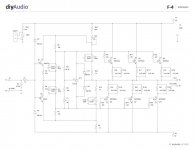
1) What are R24/25 and C3/4/103/104 for?
2) Why are they not used in BA-3 complementary OS for example?
3) When using BA-3 FE can I loose R12/13 and C3 of BA-3 FE as well as R1/2, D3/4 and input jfets Q1/2 of F4?
Any insight is greatly appreciated ;-)
Cheerio
theRog
1) What are R24/25 and C3/4/103/104 for?
2) Why are they not used in BA-3 complementary OS for example?
3) When using BA-3 FE can I loose R12/13 and C3 of BA-3 FE as well as R1/2, D3/4 and input jfets Q1/2 of F4?
Any insight is greatly appreciated ;-)
Cheerio
theRog
referring to this one , photobucketed in first post?
also , place link to ref. BA3 FE schematic
also , place link to ref. BA3 FE schematic
Attachments
Last edited:
yes indeed, referring to the one you just posted.
Forget about C103/104 I guess those are place holders for different footprints of C's on the PCB.
and here's the link to BA-3FE schematic I am refering to:
https://cdn.shopify.com/s/files/1/1006/5046/files/P-BAGSN-1V20-schematic.pdf
Forget about C103/104 I guess those are place holders for different footprints of C's on the PCB.
and here's the link to BA-3FE schematic I am refering to:
https://cdn.shopify.com/s/files/1/1006/5046/files/P-BAGSN-1V20-schematic.pdf
Last edited:
A few detail questions for the ones in the know:
1) What are R24/25 and C3/4/103/104 for?
2) Why are they not used in BA-3 complementary OS for example?
3) When using BA-3 FE can I loose R12/13 and C3 of BA-3 FE as well as R1/2, D3/4 and input jfets Q1/2 of F4?
Any insight is greatly appreciated ;-)
Cheerio
theRog
1. remember that F4 is made to be driven from something else , not sharing PSU rails ......so - let's say that I'm idiot user , connecting Good Ole
 , set to max gain ad fed from +/-36V rails ....... having two shots too much , Volume Pot is my relief and - voila ! - poor input JFet buffer is banged way above and below own PSU rails
so to connect that seesaw in manner not so dangerous for input buffer , Papa did what he did
think what's happening when input is driven with enormous swing
2. intended to be driven with more brain , but also from stage sharing same rails , so not being able to overshoot them (by much)
3. from pdf you linked - R13 is necessary - doing I/V conversion of BA3 FE output stage action , so it must stay ; more ohms - more swing...... so , R12 and C3 can go with the wind from BA3 FE ,and connect output node ( mosfet drains) ditto to common point of C1 and C2 in F4
remove input JFets , everything else can stay without any harm
Is the mosfet matching done by the diy store sufficient to parallel the 0.47 ohm resistors? If so I assume the new bias point would be 1/2 the current setting say 0.137 volts instead of 0.275 volts.
- Home
- Amplifiers
- Pass Labs
- A guide to building the Pass F4 amplifier