With all the steel screws holding the Hifi2000 style chassis together, I haven't seen any issues with various pieces being electrically connected to one another. The steel brackets make good connections all around.
PARTS QUESTIONS:
I'm collecting parts for an F4 build and noticed that R15 of the PCB V2.8 is imprinted with the designation "TB-218917". Does anyone know what this means? The BOM simply indicates that a 100R 1/4W resistor is needed. Is it safe to use a standard resistor here, or is something special indicated? I apologize in advance for asking a dumb question.
Also, the Build Guide makes reference to Vishay Dale RN60 and RN55's. They seem to be replaced by CCF50, AND CCF60's that in 1/4 W look very different. Are all Vishay metal Film resistors equally good? I read somewhere that lower wattage resistors are better tan higher wattage resistors in audio circuits as long as they meet specifications.
If you can't find RN60 or Rn55, search for the CMF series. They are basically
the RN without mil spec rating.
For the gate resistors (like R15), just use a standard 1/4 watt one (CMF or RN
if you are going to get them)
Cheers,
Dennis
the RN without mil spec rating.
For the gate resistors (like R15), just use a standard 1/4 watt one (CMF or RN
if you are going to get them)
Cheers,
Dennis
If you can't find RN60 or Rn55, search for the CMF series. They are basically the RN without mil spec rating...
FWIW, they're exactly the RN without the mil spec marking. From the Vishay datasheet: "(Except for marking, the Industrial and Military versions are exactly the same)."
Hello everyone. I have built the F4 amp in the DIY deluxe chassis from the disystore. The amp sounds great to me but I would like to take some measurements. I have read that one can subtract the incoming waveform from the output to see the distortion left behind. That image is attached, but I have no reference of what is consider good or bad. The other attached image is a FFT of the output waveform. Both input signals are a 1K Hz sinewave. In my lab there is a power analyzer, which I could hook up to the amp on a Friday, if anyone thinks that would be helpful.
I had a few hiccups during the build, but overall things went smoothly. For example I used non-matched JFETs on the input buffer and the amp sounded like electronic garbage. The matched pair of Toshiba JFETs from punkydawgs saved the amp! The power MOSFET were not matched and due to this, I believe, the voltage drop across the 0.47 Ohm power resistors are not the same. Does the voltage differences effect the quality of the sound and can it be fixed by change the resistors?
This is what I recorded across the resistors:
LEFT RIGHT
R16 0.200 0.181
R17 0.125 0.180
R18 0.143 0.181
R19 0.153 0.171
R20 0.154 0.173
R21 0.161 0.200
Can anyone recommend an analog VU meter? I would like to install a pair to complete the build. I found this chassis (luxury Full aluminum power amplifier chassis with double VU meter for AMP diy | eBay) while looking for some meters. I kind of wish I had purchased that guy instead of the deluxe chassis. The build quality of the chassis from the store is great, but most of the hardware they provided with it doesn't fit...
Attachments
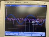
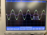
I have read that one can subtract the incoming waveform from the output to see the distortion left behind.
...with a distortion analyzer. It has a very steep and deep notch filter at the fundamental frequency, subtracts that, and what you get left over is the wave without the big signal; the "distortion residual."
You can run an FFT on the amp's output signal like you are trying, but it's very rare for anything other than a megabuck scope to have the vertical resolution to see that deep. Almost all digital scopes have 8-bit vertical resolution, that's not even remotely enough to see something that's 80db or more down from the signal, because 8-bit can't see anything more than 48db.
As for VU meters, eBay is a good place to start.
Yikes, so something like this Build a Basic Audio Distortion Analyzer | Nuts & Volts Magazine
Is there any advantage to measuring the distortion level, other than my own peace of mind?
Will there be any noticeable benefits to making the voltage drop across the source resistors equal?
Last question, for this post... Has anyone used TVS or zener diodes to clamp input signal?
Is there any advantage to measuring the distortion level, other than my own peace of mind?
Will there be any noticeable benefits to making the voltage drop across the source resistors equal?
Last question, for this post... Has anyone used TVS or zener diodes to clamp input signal?
Yikes, so something like this Build a Basic Audio Distortion Analyzer | Nuts & Volts Magazine
Neat! But there's more modern tools that will be cheaper and work better (Quant Asylum QA400 comes to mind)
Is there any advantage to measuring the distortion level, other than my own peace of mind?
Nope. But it's cool, so don't let that stop you. 🙂
Will there be any noticeable benefits to making the voltage drop across the source resistors equal?
Yes. No current hogging of the bias by one device, better balance across the mosfets, better operational characteristics.
Last question, for this post... Has anyone used TVS or zener diodes to clamp input signal?
Yes, but on an F4 it's not needed, as there's no gain for a too-big signal to blow out the output stage... if you want full power you'll need 40v pk-pk on the input.
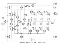
on the F4 r0 schematic, input is clamped to supply voltage through 1N4148, D3 and D4 .... Has anyone used TVS or zener diodes to clamp input signal?
Attachments
Ohh, I didn't even realize that was the purpose of those diodes. I wanted to ensure that JFETs were not damaged due to ESD or from the tube preamp I am using for the voltage gain. The power MOSFETs have their source to gate clamped with zener diodes (D1 and D2) and I wanted to ensure the more expensive JFETs are also protected!
Elliott mentions using Zeners to clamp the output of the tube preamp here: Project 167
Both TVS and zener diodes will have some amount of leakage current that passes through them, which could potentially cause some noise or distortion. So there is a trade off if they are used, much like anything else.
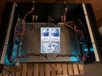
I just watched 6L6's YouTube video from Burning Amp 2018 and it has inspired me to post a picture of my ongoing F4 build. Coincidentally, the release of the Amp Camp Amp is what lead me to build the F4, despite not having built the ACA! The F4 is my first solid state amp I build from components and it has been a great learning experience (& one that is no where complete). I was a little nervous about posting a picture of my project because I did not exactly follow the build guide and didn't want to upset any of the audiophiles here (the pic has been censored just in case).
Currently I am using the DIY ECC802S (12AU7 / ECC82) Vacuum Tube SRPP Preamplifier to provide the voltage gain for the F4. I had made the 4S Universal Preamplifier for 12A*7 Tubes prior to building the F4 and it did a decent job driving the F4 however the ECC802S SRPP has way less distortion.
Currently I am using the DIY ECC802S (12AU7 / ECC82) Vacuum Tube SRPP Preamplifier to provide the voltage gain for the F4. I had made the 4S Universal Preamplifier for 12A*7 Tubes prior to building the F4 and it did a decent job driving the F4 however the ECC802S SRPP has way less distortion.
Attachments
“Not following the build guide...?” Who cares! You built your amp, it works, everybody want to see what you did and how you did it!
Looks like you used switchers for power, LOTS of people are interested in that, please tell us all about it! 🙂 🙂 🙂
My entire point about the photos is to show all the wonderful ways these can be built, and that threads with lots of photos get more engagement.
As for upsetting the Audiophiles... um, this is DIY, we’re the happiest guys in all of audio. The audiophiles are already upset because they believe in voodoo, whereas we take control, educate ourselves and actually understand what actually makes a difference 😀 😀 😀
What Jim said.
The guides are references to help people get started, and to answer questions
and point out potential pitfalls. People should not be slaves to them.
Have fun with the rest of your construction. Perhaps some non-pixelated pics
sometime?
Cheers,
Dennis
The guides are references to help people get started, and to answer questions
and point out potential pitfalls. People should not be slaves to them.
Have fun with the rest of your construction. Perhaps some non-pixelated pics
sometime?
Cheers,
Dennis
...... educate ourselves and actually understand what actually makes a difference 😀 😀 😀
speak for yourself ... I'm finding that I'm happiest simply thinking that my amp is best one , without involving elbow grease or , God forbid!!! - even slightest mental efforts

... I'm finding that I'm happiest simply thinking that my amp is best one ...
You mean it's not?
😀 😀 😀
- Home
- Amplifiers
- Pass Labs
- A guide to building the Pass F4 amplifier