I am pleasantly surprised to hear others are interested in using SMPS for audio. I'd be happy to help out builders and write more about using them for audio applications. To put it simply, the main difference of a 'switcher' to that of a standard transformer and rectifier is that the pulses of AC are much higher than 120/100Hz (for FWB and 60/50 for half-wave rectifier). There are a lot of advantages of using a good quality SMPS and of course some disadvantages; the biggest being that you don't get to build it yourself! (check out http://www.ti.com/lit/an/snaa057b/snaa057b.pdf)
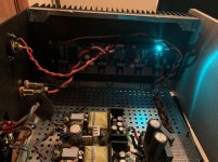
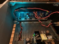
My first choice was to use two Mean Well LRS-100-24, however they were out of stock (at Mouser, where they are crazy cheap) and my patience got the best of me. I did purchase an Antek AS-4222 (400VA 22V) transformer to perform some comparisons in the future (or build another amp!). The SMPS I used for my build are two (one for each rail) Mean Well EPS-65-24, which are rated for 65.04W 24V 2.71A each. I believe this is the bare minimum power needed, if not underrated for the F4. I have yet to drive my amp to it's full capabilities at this time to see if there is an issue. Although, using this potentially underrated power supply allows for some forgiveness. For example if one makes a mistake when tinkering with the amp circuits or if your tube pre-amp gets turned on while the power amp is running, hiccup mode with auto recover to the rescue! I have yet to blow any input fuses, but I have toasted a couple of TL431 and a set of MOSFETs... 🙄
Even though the switching frequency of this power supply is above the audio band one still needs to add addition filtering. Filtering cost money, so most manufactures will use the bare min to pass federal standards. There are many ways to do this and I am looking to see what is the most effective for audio. In my build I am using a ferrite clamp on the AC input to the power supply (the clamp would have been more effective if I had used longer wires and looped it through the clamp, but I had already cut, crimped and solder everything together). I did a test to hear if there was any difference without it and the only time I heard noise was when I was physically touching the clamp to remove/attach it (my body acted like an antenna and induced audible noises). Just because one cannot hear the difference with and without doesn't mean it is not working, because the type of noise it's filtering out is above the audio range! There are three types of capacitors being used on the output of each module. A ceramic 22uF/50Vdc (RDEC71H226MWK1H03B) cap is soldered directly to the pins of the unit. Following that is a 5600uF/35Vdc electrolytic (EKYB350ELL562MMP1S) and a lower voltage film cap that I had left over from building passive crossovers (I don't remember the exact value or part number). Some SMPS manufacturers will list the max capacitance load their units can handle, but Mean Well did not so I am starting small. Once I can make some better performance measurements I will start adding more capacitors to see if there is any change.

Just like the diode bridges (and the rest of the PSU) are in a bipolar linear - the supplies are in series, and the middle is magically called "ground", because ground is where we say it is.
Yep, the negative of the positive supply is tied the positive of the negative supply, which makes the return (aka the ground here in the USA). Any smps that has an isolated output (from the input) can be wired in series. You can even create a higher volatage potentials by doing this but one should add diodes inbetween the units (although that’s off topic).

I asked this question somewhere else and they made it sound like it was impossible and in my mind, not worth trying.
I forgot to say thanks.
I forgot to say thanks.
Last edited:
Interesting topic - how best to use SMPS power supplies to provide +/- rail voltages. On one hand, one of the favorite amps of the community, the ACA, is powered by a simple but effective brick style SMPS. Since these units are fully enclosed and usually external to the rest of the amp, they tend not to cause audible interference from either mains or their internal switching frequency.
However, ‘stacking’ a pair of SMPS units inside a chassis to make +/- power rails has extra challenges. Since the switching frequencies of a pair of units do not exactly match each other, multiple beat frequencies consisting of sums and differences of the primary will be present. The beat frequencies will be conducted by the power wires, and may also be radiated by unshielded units. Using enclosed SMPS units will help greatly reduce the radiated interference. Conducted interference needs to be attenuated by filtering and / or regulation.
If I were stacking SMPS units, I would probably use a capacitance multiplier to filter each power rail.
Metal enclosures will help shield radiated noise and in fact there are enclosures made for that unit for a $$. I choose not to use one because of the spacing between the amp board and pwrsply. Using a capictance mulitplier would be a great way to increase the as seen total farads to the amp all while keeping the starting surge of the smps within its limits. I will use the the remaining portion of my pref board to build one!
Metal enclosures will help shield radiated noise and in fact there are enclosures made for that unit for a $$. I choose not to use one because of the spacing between the amp board and pwrsply. Using a capictance mulitplier would be a great way to increase the as seen total farads to the amp all while keeping the starting surge of the smps within its limits. I will use the the remaining portion of my pref board to build one!
May I recommend:
HRP-100-24 MEAN WELL | Mouser
These units may be mounted on their side if necessary. But that’s a nice big chassis you have with plenty of options, including the inside of the front panel.
Here's another one: Mean Well MW LRS-200-24 24 VDC 8.5A 200W Regulated Switching Power Supply with Power Cables
30 bucks for 200w.
If it's not too much to ask or too much work, can someone draw up a schematic of what a dual supply SMPS would look like with added CapX or extra caps or parts?
Maybe a minimum, low noise working supply?
Here's the thing. I used Mean Well SMPS in MoFo amp mono-blocks and they sound great. No complaints from me. (Still curious what a linear supply would do...)
If people can build a dual 24v power supply out of inexpensive SMPS, people would try more First Watt amps. Maybe build themselves a universal chassis and switch amp boards without worrying about the supply. If they want to try linear supply, then they can build one later. I know, people have already done the same with linear supplies.
However, SMPS cost less, save space, have less wiring involved and less supporting parts. They also have some built-in protection... I think. A CapX might complicate things a little but whatever. If dual supplies are possible, I see many positives to SMPS and little on the negative side.
Thanks in advance.
Vince
Last edited:
There are many positives, absolutely.
The negatives include -
Beat frequency interactions down into the audio band
Radiated noise (RF)
If one fails, the entire other rail will appear on your speaker as DC.
In the time being, issues such as this are why the linear supply will always be the standard.
These are not insurmountable issues, but do require some attention. There's been some look into it, and believe me, I'd love to see something like an interface board in the amp chassis that takes 2 of the external 24v 150w bricks that the ACA uses to make a bipolar, while providing filtering and shutdown protection. No AC wiring at all? That would be great.
However, as soon as you add complexity you add cost, and fairly soon the normal linear PSU doesn't look like a big deal anymore.
You mention a universal chassis where you don't have to worry about the supply - The last couple build guides have been exactly that. 🙂 Chassis/PSU/Transformer are all the same, I'm just swapping amp PCBs. 😀 Works great! 😀
There' no question in my mind that there will be a solution to use SMPS in these projects with minimum or no downside. I'm looking forward to that!
Looking at your linked PSU (MW LRS-200-24) I'm very tempted to get two and just try it.
Last edited:
simplicity means efficiency means lesser headache
so , I agree with Jim 🙂
one rail - decent SMPS is ok
two rails - decent bipolar SMPS (made for purpose, so no more cheap) is OK ..... anything different than that is just greater headache ...... two stacked single rail SMPS-they're practically two different entities just sometimes working in unison
so , I agree with Jim 🙂
one rail - decent SMPS is ok
two rails - decent bipolar SMPS (made for purpose, so no more cheap) is OK ..... anything different than that is just greater headache ...... two stacked single rail SMPS-they're practically two different entities just sometimes working in unison
When I have some extra time I can put together a little schematic and include some ways to add filtering. In the mean time if you go to Delta Power Supply - How to Operate Parallel and Series Connection - Delta Power Supply section 2. Series Operation and just use the node -V1 tied +V2 as the return (ground).
In my opinion using two 200W is not warranted because SMPS are happier with at least a 10% load (although MW claims their units will run fine at 0%), higher power ones will typically have more ripple and poorer regulation. If you are looking for something cheaper than the HRP-100-24, take a look at the LRS-75-24. The HRP cost more because it has some additional features, like built in remote on/off control and power factor correction.
Sounds like using the Speaker Turn-On Delay and DC Protector is good idea if one will be using dual SMPS.
Here are a couple of articles regarding what we have been discussing.
http://carvermk2.com/Docs/Carver Magnetic Field Whitepaper.pdf (It's an older paper but has some great info)
https://www.calex.com/pdf/3power_impedance.pdf (This talks about decoupling power supplies and has great info regarding the different types of capacitors)
@6L6
Well, there you go. That's why I'm In on a group buy for dual supply on one board PCBs. Gotta keep the train moving. 😉
Thanks.
Well, there you go. That's why I'm In on a group buy for dual supply on one board PCBs. Gotta keep the train moving. 😉
Thanks.
Alternate First Watt Power Supply Schematic
See last page for recent discussion on having some boards made.
See last page for recent discussion on having some boards made.
What about putting a low pass filter in the SMPS output to get rid of the HF ripple? Big cap+choke. How would that compare with a cap mx?
- Home
- Amplifiers
- Pass Labs
- A guide to building the Pass F4 amplifier