If you'd give some advice, for one 8" driver per side (two per speaker), what would be the diameter of one hole? Let's say i have not decided on what specific driver the 8" will be.
I plan to leave the enclosure open on the back side for the 8" drivers, to fire back, as in a dipole, as Xrk did on one of his builds.
The xo points for the 8" are 120Hz and 320Hz.
Thank you!
Well there are a few factors involved and it's a tradeoff:
1. Hole needs to be large enough so that you don't have too much compression effects which cause a large bandpass overshoot spike at the HF cutoff.
2. Hole needs to be large enough to prevent chuffing at high SPL, try to keep velocities below 25m/s, some prefer 10m/s to 15m/s. Smaller the hole, the higher the velocity.
3. Hole needs to be as small as possible to reduce effects on waveguide performance for directivity.
Some rules of thumb: make total hole cross sectional area about 20% of cone Sd (typical bass reflex boxes use 33% Sd on ports); drill holes perpendicular to horn wall to reduce exaggeration of hole CSA due to cosine(theta) effect. In my case, the wall goes up at 60 deg angle towards one side and I ended up with a hole CSA that is maybe almost 2x what I intended.
Having said all that, I have simulated hole diameters ranging from 32mm dia x qnty 2 to 65mm dia x qnty 2 and they can all work. the 32mm dia will limit max SPL with chuffing, and the large 65mm dia will give the horn wall some massive missing wall area. I think Bushmeister went with 60mm dia. I went with 50.7mm (2.0in dia). Pick a common size so you can find a hole saw.
If lower volume domestic levels of SPL are intended purpose (85dB to 95dB), go with smaller hole (36mm is a good tradeoff) to keep horn wave guide clean. Go with larger holes if intending to do 110dB SPL.
So 2x36mm holes in diameter for each 8" driver. Yes, 85 to 95 is absolutely good.
Thank you Xrk! These multi-point threads you created are GOLD! I think a major turn in diy speaker future builds.. At least for me they are.
Thank you Xrk! These multi-point threads you created are GOLD! I think a major turn in diy speaker future builds.. At least for me they are.
And one more question i forgot to ask earlier. The distance from throat, i should drill the center of the hole at 1/4 wavelength of crossover frequency or is it better to add or substract a little from this value?
How about using 4.5.6. 8 holes with smaller diameter? Less diffraction and higher portvelocities allowed?
Hi X
Great effort! I agree with schmutziger. Replace those big holes with a lot of very narrow holes. This should make the ports 'invisible' to HFs.
Great effort! I agree with schmutziger. Replace those big holes with a lot of very narrow holes. This should make the ports 'invisible' to HFs.
Sorry for the silence chaps. I am busy polishing ports, rubbing down the horns to get rid of the gloss and give them a nice Bakelite appearance, making the stereo pair etc.etc.
I have done further measurements with and without the 2mm felt circle which is on the outer lip of the routed horn throat, and it definitely smooths the freq response, but I suspect this is a result of my technique, as X didn't modifiy the horn throat itself.
I should be getting a large delivery of 18mm Baltic birch ply this weekend, so then cutting will start.
I have decided to make normal cuboid boxes rather than trapezoid as the way the woofers are mounted will actually result in less backwave reflections if the back wall is rectangular.
I promise as soon as I make significant progress I will update. But for the moment I am just completing the second horn and putting nice finishes on.
Ps - X, great work on the filler plug, looks amazing, but I found I didn't need it, so might be worth measuring without first to see whether it is worth printing more.
How about using 4.5.6. 8 holes with smaller diameter? Less diffraction and higher portvelocities allowed?
Good idea, maybe my repair 3d printed plug can have multiple smaller holes? Actually, this method allows me to print various hole size combinations and test.
And one more question i forgot to ask earlier. The distance from throat, i should drill the center of the hole at 1/4 wavelength of crossover frequency or is it better to add or substract a little from this value?
That's the technical way to do it per theory, also important to time align, but in practice if you have DSP and ability to adjust time delay the dominant factor is a practical one: the holes need to be where the woofer cone has access to them as you will find there is basically only one position to mount woofer. I put mine about 2.25in back from mouth exit plane (centerline).
These multi-point threads you created are GOLD! I think a major turn in diy speaker future builds.
Thanks for the kind words. 🙂 Judging from the number of views this thread has had, a lot of others seem to be following and interested too. I think the realization I am getting is that building these with commercial WG's makes the performance so much better than any DIY horn I can make, and it speeds up the work significantly judging from the progress that both Bushmeister and myself are having with these builds.
Last edited:
Random idea for x...
X, have you ever considered executing a replica of a Klipschorn in foam board? That could be your magnum opus 🙂
X, have you ever considered executing a replica of a Klipschorn in foam board? That could be your magnum opus 🙂
X, have you ever considered executing a replica of a Klipschorn in foam board? That could be your magnum opus 🙂
No, although that is a well regarded speaker and very sensitive but I think it's too big to make in foam. Also, I think a point source horn sounds better - coupled with a good folded bass horn for below 100Hz, this little bookshelf speaker can do quite well. This is the new speaker to build -give it a try.
X, do you recommend specifically a folded horn bass for matching sensitivity, or some other reason? Those of us with sealed subs but kilowatts available for aforementioned low frequency transducer wish to know your logic. Thank you sir 🙂
If you have sealed subs and gobs of amp power that works too. The sound is different though - have you seen how much harmonic distortion a sealed sub makes when producing 100dB at 40Hz or 50Hz? A properly designed bass horn is capable of less than 0.5% THD at 100dB and 1m. Mostly because the horn loading keeps the cone from barely moving so less stroke, means less HD. Same goes for the top horns. That is the magic of all horn systems - high sensitivity, and low HD (well, when using full range drivers for tweeters anyhow, compression drivers don't fare as well in the HD department).
If you do the hols square, u can try slot ports and if you put the port ofcenter try diffrent portplacings.Good idea, maybe my repair 3d printed plug can have multiple smaller holes? Actually, this method allows me to print various hole size combinations and test.
I suggest a small chamfer on the ports (both sides)to optimize them for high speeds.
And, great thread!
Last edited:

Good idea, maybe my repair 3d printed plug can have multiple smaller holes? Actually, this method allows me to print various hole size combinations and test.
Multiple smaller holes but the same length will increase Fc.......is that desirable?
X
In hornresp the holes are divided by the number used, is this also the case here? I have ask David for it because I was not shure, a hole of 12 cm wide is to big in my eyes, I think you do divide them by two, if so, it can made smaller because you loose little or nothing say hornresp to me.
This was the last unclear thing to me, now I get the hang on it.
regards
Mwasurements with the big holes
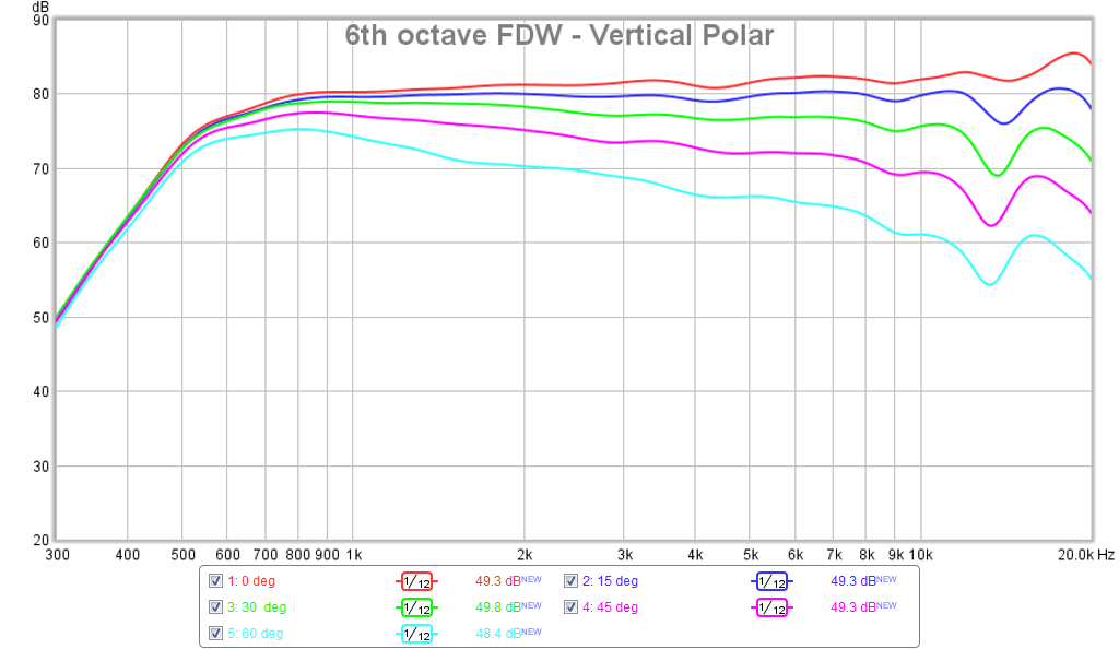
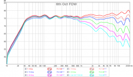
To refresh your memory, here is what the vertical orientation polars looked like before the holes were cut (0.5m distance):
Here is after the holes were cut:
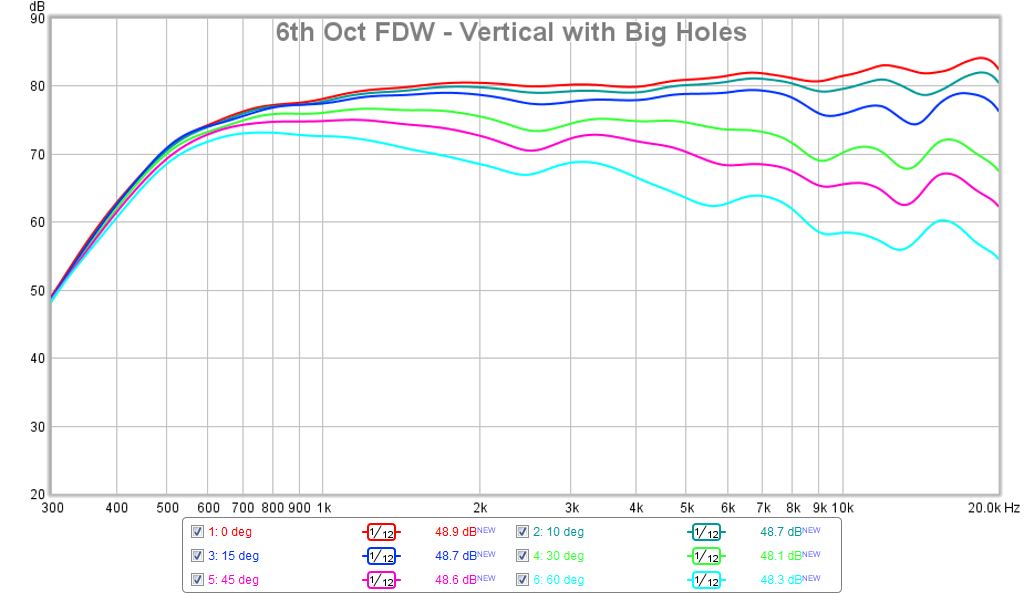
We can see that the big holes did some damage to the rather pristine polars at the larger angles - with a noticeable dip at 2.5kHz, and the lower frequency extension is not as deep. Although this horn is supposed to be 50deg in this orienation so for 30deg, it is not too bad.
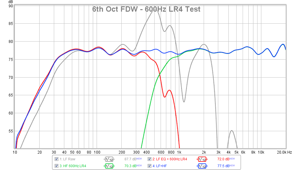
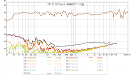
Out of curiosity, I wondered how the woofers would measure and sound with a heavy curtains draped on it. Surprising bass extension with this semi cardiod setup. This is at 10deg off axis and 0.5m away. Raw woofer response is shown in grey - the characteristic band pass overshoot peak is there and can be EQ'd out as shown in red curve which also has 5dB Q=0.8 bass low-shelf at 43Hz and 600Hz LR4 HPF. Combined with 600Hz LR4 HPF on the SB65, we get a pretty nice, albeit not transient perfect response:
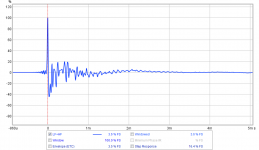
Here are corresponding IR:

Measured HD at this rather low SPL:

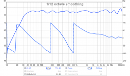
Here is measured phase typical of a 4th order Linkwitz Riley XO. The reverse polarity null (not shown) was exactly at 600Hz:

Here is corresponding polars with woofer playing:

Overall, not too bad with an f3 of 30Hz. Only had a chance to listen to a few songs, but what I hear sounds very nice. The issues with the polar plots are not readily apparent to my ears.
Here is a sound clip from the UMIK-1 recorded to Audacity and converted to mp3. Change extension from .asc to .mp3 to listen. There is some mic hiss - not sure what it's from but don't hear on speaker.
To refresh your memory, here is what the vertical orientation polars looked like before the holes were cut (0.5m distance):
Here is after the holes were cut:
We can see that the big holes did some damage to the rather pristine polars at the larger angles - with a noticeable dip at 2.5kHz, and the lower frequency extension is not as deep. Although this horn is supposed to be 50deg in this orienation so for 30deg, it is not too bad.
Out of curiosity, I wondered how the woofers would measure and sound with a heavy curtains draped on it. Surprising bass extension with this semi cardiod setup. This is at 10deg off axis and 0.5m away. Raw woofer response is shown in grey - the characteristic band pass overshoot peak is there and can be EQ'd out as shown in red curve which also has 5dB Q=0.8 bass low-shelf at 43Hz and 600Hz LR4 HPF. Combined with 600Hz LR4 HPF on the SB65, we get a pretty nice, albeit not transient perfect response:
Here are corresponding IR:
Measured HD at this rather low SPL:
Here is measured phase typical of a 4th order Linkwitz Riley XO. The reverse polarity null (not shown) was exactly at 600Hz:
Here is corresponding polars with woofer playing:
Overall, not too bad with an f3 of 30Hz. Only had a chance to listen to a few songs, but what I hear sounds very nice. The issues with the polar plots are not readily apparent to my ears.
Here is a sound clip from the UMIK-1 recorded to Audacity and converted to mp3. Change extension from .asc to .mp3 to listen. There is some mic hiss - not sure what it's from but don't hear on speaker.
Attachments
-
 SB65-LTH142-EQ-6thFDW-Polar-vertical-Big-Holes.png91.2 KB · Views: 635
 -
 SB65-DC200-LTH142-600Hz-LR4-FAST-Test.png92.5 KB · Views: 639
 -
 SB65-DC200-LTH142-600Hz-LR4-FAST-Test-IR.png50 KB · Views: 642
 -
 SB65-DC200-LTH142-600Hz-LR4-FAST-Test-HD.png133.8 KB · Views: 636
 -
 SB65-DC200-LTH142-600Hz-LR4-FAST-Test-Phase.png78.8 KB · Views: 830
 -
 SB65-DC200-LTH142-600Hz-LR4-FAST-Test-Vert-Polar.png101.6 KB · Views: 830
 -
SB65-LTH142-DC200-LR4-600Hz-FAST-Big-Holes-clip-1.asc1.6 MB · Views: 85
Last edited:
I suggest a small chamfer on the ports (both sides)to optimize them for high speeds.
And, great thread!
And to minimize HF diffraction artifacts off the hard edges- might be a 2nd or 3rd order effect but easy enough to get at them with a dremel or something. In fact, one could cut out a section of the horn and inset the spacer into that allowing for the profiling to be done in the 3d printing process.
- Home
- Loudspeakers
- Multi-Way
- A Bookshelf Multi-Way Point-Source Horn