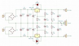
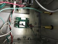
Looks correct to me. The speaker outputs from the CCS PCB and Gain PCB will obviously need to be tied together off board before going to +SPKR.
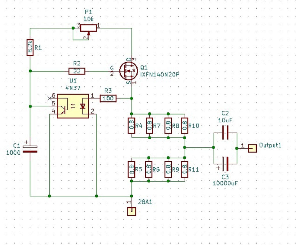
The +28V output from the CCS board will connect to "D" or pin 3 on this boards MOSFET. I caught a little hint from ZM's build. Instead of putting a solderable mounting hole on the PCB. I connect directly with a crimp on ring connector directly on the MOSFET.
Regards,
Dan


Big thanks to Dan...My KiCad/PCB fabbing addiction is in full force. I went the 317/337 route as well, but put a 'mini' PS before it.
Attachments
to MEGA_amp #1289
Looks really good!
I also made a seperate small PSU for the bias and for the input-buffer. My buffer
is outside of the 50W-SE-Schade-amp. This amp is hot!
Greets
Dirk
Looks really good!
I also made a seperate small PSU for the bias and for the input-buffer. My buffer
is outside of the 50W-SE-Schade-amp. This amp is hot!
Greets
Dirk
Big thanks to Dan...My KiCad/PCB fabbing addiction is in full force. I went the 317/337 route as well, but put a 'mini' PS before it.
When I first inquired about using KiCAD I was warned about the steep learning curve. I found the YouTube tutorials (especially John's Basement) were a huge help and made getting use to KiCAD easy.
Regards,
Dan
Good evening, gentlemen.
Where can I buy the input transformers (JT-123-FLPCH).
By thanking you in advance.
Where can I buy the input transformers (JT-123-FLPCH).
By thanking you in advance.
You can try direct from jensen, email probably works best:
High performance audio transformers and ground isolators.
I purchased mine from the link below, great service from these guys:
Jensen Transformers JT-123-FLPCH Line Output Transformer, PCB Mount
High performance audio transformers and ground isolators.
I purchased mine from the link below, great service from these guys:
Jensen Transformers JT-123-FLPCH Line Output Transformer, PCB Mount
You'll have to give me some hints. I've been off doing other things so now I'm a bit rusty!
Regards,
Dan
Regards,
Dan
Rail = power supply, relative to ground
Output node = speaker out node at the resistor string between the two mosfets, relative to ground. It should be in the neighbourhood of 30v.
If you are measuring 3.3A through the first mosfet, it must be going somewhere.
Output node = speaker out node at the resistor string between the two mosfets, relative to ground. It should be in the neighbourhood of 30v.
If you are measuring 3.3A through the first mosfet, it must be going somewhere.
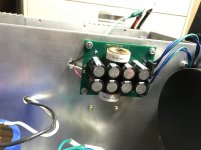
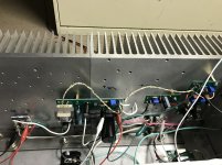
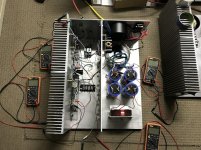
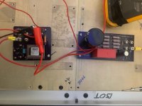
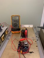
Rail voltage is 59.6 vdc. Where it's supposed to be 30v it's 1.7V.
For fun I connected a 4 ohm 500W resistor to the CCS 28 volt output alone to ground and it drew the same current (3.3A) and the current was adjustable via the pot.
The heatsink I have the mosfets mounted on is standalone and not connected to the ground of the power supply. Could that be it?
And no current flows at all until I apply about 6-7v bias to the second mosfet.
Attachments
Last edited:
Mu part is having Iq set, whatever voltage across is
you need to set bias of lower pqart of amp, to set equal voltages ( 50% of Rail voltage) across each half of amp
read Singing Bush Tips 'n' Tricks thread
you need to set bias of lower pqart of amp, to set equal voltages ( 50% of Rail voltage) across each half of amp
read Singing Bush Tips 'n' Tricks thread
- Home
- Amplifiers
- Pass Labs
- 50w Single-Ended BAF2015 Schade Enabled