feed the lower mosfet drain with +30V independent from the CCS if you can. 6-7V on the bias seems a bit high, I found somewhere between 3.8V to ~4 wakes it up properly.
feed the lower mosfet drain with +30V independent from the CCS if you can. 6-7V on the bias seems a bit high, I found somewhere between 3.8V to ~4 wakes it up properly.
Great idea. I'll do that and posts the results as soon as time permits.
Regards,
Dan
no need for separate testing , if you already confirmed that Mu half is working as prescribed
now just do what you need to properly bias lower part of amp, so drain of lower one is on intended voltage level
now just do what you need to properly bias lower part of amp, so drain of lower one is on intended voltage level
no need for separate testing , if you already confirmed that Mu half is working as prescribed
now just do what you need to properly bias lower part of amp, so drain of lower one is on intended voltage level
It isn't so I'm trying to see if I missed anything. More soon..................😱
Regards,
Dan
Am I over thinking this? Power dissipated in my lower mosfet is Rds On x (IxI)?
This means 3.2A squared is 10.4A times 18mOhms which is 184mW?
Regards,
Dan
This means 3.2A squared is 10.4A times 18mOhms which is 184mW?
Regards,
Dan
power dissipated in part is current * voltage across it
if you want to have a functional amp, you need to have so-so equal voltages across upper and lower mosfet
in contrary, you'll have just space heater
in short - you must have an amp properly set...... or just toss it through window and be done
so, instead of chasing your own tail ( and making me/us to do the same), try to elaborate - what is the problem ?
so, instead of chasing your own tail ( and making me/us to do the same), try to elaborate - what is the problem ?
Sorry, that it not my intent. I’ll wait till I have more time instead of throwing bits and pieces at the wall.
That’s what I’m guilty of right now. I’m spending 5 minutes a day on it. That’s just not working.
Thanks again.
Dan
Sorry, that it not my intent. I’ll wait till I have more time instead of throwing bits and pieces at the wall.
That’s what I’m guilty of right now. I’m spending 5 minutes a day on it. That’s just not working.
Thanks again.
Dan
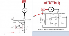
Just tinkering and posting some stuff for fun.
My CCS with a 4 ohm 500 watt resistor as a load.
VCC is right on 60VDC
Vgs is 3.44VDC
Vds is 42VDC
and circuit current is right on 3.2A
Regards,
Dan
My CCS with a 4 ohm 500 watt resistor as a load.
VCC is right on 60VDC
Vgs is 3.44VDC
Vds is 42VDC
and circuit current is right on 3.2A
Regards,
Dan
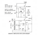
that looks about right, pretty much the same values I got for a stock CCS tested independently. You could test the lower end independently or just connect it to the CCS as ZM said, cause you at least know the CCS works. Make sure you got that 5K pot in your bias supply, or it may not go low enough to turn on the lower fet correctly...again that 6-7V that you mentioned earlier doesn't seem right.
attached pic courtesy of the Mighty ZM
attached pic courtesy of the Mighty ZM
Attachments
Last edited:
that looks about right, pretty much the same values I got for a stock CCS tested independently. You could test the lower end independently or just connect it to the CCS as ZM said, cause you at least know the CCS works. Make sure you got that 5K pot in your bias supply, or it may not go low enough to turn on the lower fet correctly...again that 6-7V that you mentioned earlier doesn't seem right.
attached pic courtesy of the Mighty ZM
Why do you have your input grounded in the second pic?
Regards,
Dan
well, whenever I'm setting up an amp or verifying proper operation, it just eliminates any unusual-ness. Plus it was from ZM...we follow him blindly😀
well, whenever I'm setting up an amp or verifying proper operation, it just eliminates any unusual-ness
🙂
...... Plus it was from ZM...we follow him blindly😀
and, yes, ZM already being half-blind ....... what's that saying about mine ...... and your intelligence?

OK. With the rest of the circuit connected as seen below without the two output wires connected.

For the CCS
Vgs is 3.24vdc
Vds is 56.7vdc
Current drawn is 3.4amps
For the bottom half
Vbias is 6.3
Vgs is 6.43
Vds is .057vdc
Regards,
Dan
For the CCS
Vgs is 3.24vdc
Vds is 56.7vdc
Current drawn is 3.4amps
For the bottom half
Vbias is 6.3
Vgs is 6.43
Vds is .057vdc
Regards,
Dan
Attachments
You may want to unhook the lower MOSFET from your circuit and test to see that is has not failed and is shorted from drain to source. I hope not, but that is one logical explanation.
- Home
- Amplifiers
- Pass Labs
- 50w Single-Ended BAF2015 Schade Enabled