maybe I overlooked ...... did you tried starting it up as complete amp, pre-set to 0V as Ugs for lower side?
What are the voltages from resistor to ground and from ammeter to ground? Maybe check with oscilloscope.
Sorry, late, late night brain fart. More accurate information soon.
Regards,
Dan
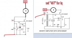
Dan, ditch the ammeter in line with anything. If you must test the upper and lower independently to verify proper operation use this attached circuit. Instead of an ammeter, put a bunch of low value power resistors in place of where the "A" is in the attached. I used 4x0.47R parallel for example. For the lower gain test, verify bias voltage is as low as you can get, apply power. Slowly bring up the bias until you measure 28VDC D-S. Connect per the schematic attached, I used this to verify, it works. The circuit as drawn in the begginning of this thread works perfectly, no need to add all these extras. I built the amp exactly, with exception of a pot in the upper Mu, it works.
Attachments
Dan, ditch the ammeter in line with anything. If you must test the upper and lower independently to verify proper operation use this attached circuit. Instead of an ammeter, put a bunch of low value power resistors in place of where the "A" is in the attached. I used 4x0.47R parallel for example. For the lower gain test, verify bias voltage is as low as you can get, apply power. Slowly bring up the bias until you measure 28VDC D-S. Connect per the schematic attached, I used this to verify, it works. The circuit as drawn in the begginning of this thread works perfectly, no need to add all these extras. I built the amp exactly, with exception of a pot in the upper Mu, it works.
Sorry about last nights ramblings. I was overtired.
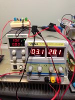
Back to basics. With the ammeter removed the CCS works perfectly with the 4R0 test resistor. I'm monitoring current with Dirk's Ohms law suggestion. Resistor voltage drop (around 1.37vdc) across 0.407 Ohms. About 3.36 amps.
Next step is add the lower half with an external power source feeding the bias.
Going to leave the ammeter out of testing the whole circuit and adjust bias for a Vds of 28v on the lower MOSFET.
Regards,
Dan
Added the lower half of my circuit with no bias. Blew the 4A fuse and toasted both MOSFETs. I now know my CCS has no design flaws and works perfectly. After reviewing the lower half of my circuit I"m going to do any future testing with two labs supplies. One for the 28V and one for the bias. Not the CCS.
More when time permits!
"The road to hell is paved with burnt MOSFETs!" Dan Twomey 2020
Regards,
Dan
More when time permits!
"The road to hell is paved with burnt MOSFETs!" Dan Twomey 2020
Regards,
Dan
2) The DC Drain voltage of the circuit's gain transistor is temperature
dependent, but it generally should be fairly stable if the heat sinking is
adequate - If it's not stable enough you can put a 5 or 10 watt 220 ohm
resistor from Drain to Source to stabilize it better. I don't think you need
the complexity of a servo.
Tried a 220R5W D to S. It seemed to help quite a bit.
Regards,
Dan 🙂
Last edited:
Excellent, seems like all is well. Yes, when testing the lower end without the CS, I noted a runaway as well when trying to set the bias, its extremely sensitve. Make sure you note what that bias voltage was, as thats what you'll use when you connect the CS. Now connect it all up, with fuse, and maybe a light bulb in line with your transformer primary....and keep the ammeter away!!
Excellent, seems like all is well. Yes, when testing the lower end without the CS, I noted a runaway as well when trying to set the bias, its extremely sensitve. Make sure you note what that bias voltage was, as thats what you'll use when you connect the CS. Now connect it all up, with fuse, and maybe a light bulb in line with your transformer primary....and keep the ammeter away!!
Very interesting.......
 As part of my pursuit of happiness here I’m thinking of making a ‘stripped down’ PCB that is an exact duplicate of the lower half of the original drawing. This has, and continues to be quite a learning experience!
Regards,
Dan 🙂
P.S. Many thanks to ZM. I think I’ve tested his patience at times.
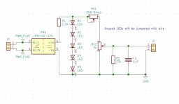
The Mighty ZM has 'inspired' me to do some tinkering while I'm waiting for more parts. This circuit also got me thinking on whether or not these 1W or 2W DC power modules are 'easier' or 'cheaper' when it comes to supplying low ma bias circuits...................😉
Regards,
Dan

Regards,
Dan
Attachments
These MeanWell devices are cool....
https://www.meanwell.com/Upload/PDF/IRM-01/IRM-01-SPEC.PDF
Much higher current series:
https://www.meanwell.com/Upload/PDF/IRM-15/IRM-15-SPEC.PDF
https://www.meanwell.com/Upload/PDF/IRM-01/IRM-01-SPEC.PDF
Much higher current series:
https://www.meanwell.com/Upload/PDF/IRM-15/IRM-15-SPEC.PDF
These MeanWell devices are cool....
https://www.meanwell.com/Upload/PDF/IRM-01/IRM-01-SPEC.PDF
Much higher current series:
https://www.meanwell.com/Upload/PDF/IRM-15/IRM-15-SPEC.PDF
For a specific voltage supply that only requires a few ma they could beat the cost and complexity of getting your own small VA transformer, a bridge, some caps, etc. They are a nice option.
Regards,
Dan 🙂
Agreed! I’ve been wanting to try them. You could build a very small, but quite PS with a simple CLC supply, if necessary.
Dan, ditch the ammeter in line with anything. If you must test the upper and lower independently to verify proper operation use this attached circuit. Instead of an ammeter, put a bunch of low value power resistors in place of where the "A" is in the attached. I used 4x0.47R parallel for example. For the lower gain test, verify bias voltage is as low as you can get, apply power. Slowly bring up the bias until you measure 28VDC D-S. Connect per the schematic attached, I used this to verify, it works. The circuit as drawn in the beginning of this thread works perfectly, no need to add all these extras. I built the amp exactly, with exception of a pot in the upper Mu, it works.
John,
In future designs I may include the following on certain PCBs.
https://www.mouser.ca/ProductDetail/144-FH-320-NV/
Although I have used ones in the past that have a minature LED that lights
when the fuse blows. I haven't seen any of those yet.
Merry Christmas

Dan
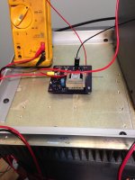
R3 burned on startup. The 6.8K are bleed down resistors on the power supply.
The road to success is paved with...................😱
I have a specific plan.
Lots of details and porn later..............🙂
Regards,
Dan
Dear sir,which 6.8K resistor are you talking about?
Dear sir,which 6.8K resistor are you talking about?
The bleed down resistor for the power supply. If you review some of the pics I've posted you'll see it attached to the bridge rectifier.
Regards,
Dan
Bleeder resistor - Wikipedia
BTW - Chengdu is one of our favorite places to visit. 😀 Lovely people, wonderful food, gorgeous mountains and rivers.
BTW - Chengdu is one of our favorite places to visit. 😀 Lovely people, wonderful food, gorgeous mountains and rivers.
- Home
- Amplifiers
- Pass Labs
- 50w Single-Ended BAF2015 Schade Enabled