Did you try setting the bias on the lower MOSFET to 0 with the circuit complete and then gradually increasing the bias while monitoring the current at the other MOSFET's source resistors? You can calculate the current that way and work your way up.
Your schematic shows a 22k gate resistor. Is that what you have? Don't know if that would affect any oscillations, though.
1nF from CCS mosfet Drain to gate resistor
put damn 4A fuse in positive rail, fast one
Great minds think alike? I put a 5A inline fuse in and it died and the MOSFET did too. 😱
BTW. The inline fuse was quite happy through the whole testing process with the resistor and then with the second half of the circuit. Once again, as soon as the circuit was connected (sans ammeter) directly to ground, death ensued!
Regards,
Dan
Your schematic shows a 22k gate resistor. Is that what you have? Don't know if that would affect any oscillations, though.
Drawing is a little fuzzy. A close up will show you 22R.
Regards,
Dan 🙂
try entire shebang as whole, with lower mosfet biasing voltage at minimum, for start
include mentioned cap at CCS mosfet, put even smaller (fast) fuse in positive rail
include protection zenner for mosfet gate (post #3 in Singing Bush thread)
include mentioned cap at CCS mosfet, put even smaller (fast) fuse in positive rail
include protection zenner for mosfet gate (post #3 in Singing Bush thread)
try entire shebang as whole, with lower mosfet biasing voltage at minimum, for start
include mentioned cap at CCS mosfet, put even smaller (fast) fuse in positive rail
include protection zenner for mosfet gate (post #3 in Singing Bush thread)
Hmmmmm... I'm wondering if it would be worth my time and effort to redo my CCS PCB...........😕
It would be an opportunity to learn how to do fill on PCBs rather than just lines.
Regards,
Dan 🙂
cap and zenner, that's trivial to add on existing traces
Will do. 🙂
Great minds think alike? I put a 5A inline fuse in and it died and the MOSFET did too. 😱
BTW. The inline fuse was quite happy through the whole testing process with the resistor and then with the second half of the circuit. Once again, as soon as the circuit was connected (sans ammeter) directly to ground, death ensued!
Regards,
Dan
Dan this is a puzzler indeed. Just curious - do you swap out the ammeter hot or with the amp fully powered down (and with caps discharged) before swapping and then power up ?
Part 2
..... The main power supply feeds the 'D' screw with the 60VDC and I take the output of the CCS to a 4R0 500W resistor then through my Fluke meter to ground. ......
I don't know whether this makes a difference or not but the bottom half of the circuit should drop about 28V. Therefore for a realistic test load, R=28V/3.2A= 8.75R
Part 4
.........I connect the bottom half of the circuit to the CCS and use the bias to carefully adjust the current through the second MOSFET to the desired 3.2A. .........
My understanding is that once the bottom Mosfet starts conducting, the current will stabilize. What needs to be monitored is Vds of the lower Mosfet. Adjust bias until Vds=28V. Start with Vbias at maximum, then reduce Vbias and watch Vds reduce down to 28V.
Another point, did you connect "Speaker Output" of the lower board to "Output1" of the upper board?
Also, take the ammeter out out the equation during both tests. Measure the voltage drop across the four 0.8R in parallel to determine current. 0.2R x 3.2A = 0.64V.
Last edited:
Dan this is a puzzler indeed. Just curious - do you swap out the ammeter hot or with the amp fully powered down (and with caps discharged) before swapping and then power up ?
With the amp powered down. It is indeed puzzling because with the Fluke meter in place everything appears to work exactly as it was designed.
Regards,
Dan
Dan this is a puzzler indeed. Just curious - do you swap out the ammeter hot or with the amp fully powered down (and with caps discharged) before swapping and then power up ?
I don't know whether this makes a difference or not but the bottom half of the circuit should drop about 28V. Therefore for a realistic test load, R=28V/3.2A= 8.75R
My understanding is that once the bottom Mosfet starts conducting, the current will stabilize. What needs to be monitored is Vds of the lower Mosfet. Adjust bias until Vds=28V. Start with Vbias at maximum, then reduce Vbias and watch Vds reduce down to 28V.
Another point, did you connect "Speaker Output" of the lower board to "Output1" of the upper board?
Also, take the ammeter out out the equation during both tests. Measure the voltage drop across the four 0.8R in parallel to determine current. 0.2R x 3.2A = 0.64V.
The ‘speaker outputs’ were tied together for the test of the full circuit. After I had the full circuit running with the ammeter in place I was drawing very close to 3.2A and the Vds of the lower mosfet was about 27.6vdc.
Regards,
Dan
Start with Vbias at maximum, then reduce Vbias and watch Vds reduce down to 28V.
Whoops, I was thinking of the THF-51S. With the IXFN, it is the opposite. Start with Vbias at 0 and increase Vbias to reduce Vds. Just to set the record straight.
Just a wild thought but since the CCS mosfet fried at turn-on with no ammeter after no issues with the ammeter in place, did the capacitor at the speaker output have a chance to fully discharge? Since the ammeter was the connection to ground, removing the ammeter would stop the discharge. Connecting the ground would continue the discharge but if power was applied quickly perhaps the capacitor might not be fully discharged. Just thinking that perhaps a bit of charge in the capacitor might affect start-up routine and slightly delay the setting of Vgs of the CCS mosfet so that it passes a massive burst of current and fries before Vgs stabilizes.
Just a wild guess.
When I tested my amp, I had an 8R resistor at the speaker output paralleling the 220R so the capacitor discharged quite quickly at power down.
I think the principle we're touching on here is the 'amplifier' cannot be energized or de-energized without a load connected?
Regards,
Dan

hardly - if Papa published circuit..........
you're having some methodical omission here, circuit is working
you're having some methodical omission here, circuit is working
To adjust a similar circuit I used a variac transformer, I gradually increased the voltage and controlled the voltage and the current across the transistor.
hardly - if Papa published circuit..........
you're having some methodical omission here, circuit is working
Good point. I find when troubleshooting it’s wise to boil down the problem to it’s simplest form. After implementing ZM’s cap and zener trick I’m going to strip the PS down to the bare main 60vdc supply. When it’s time for bias I’m going to use one of ZM’s greenies fed by an external lab supply. You can’t get much simpler than that. More details soon.......
Regards,
Dan
Last edited:
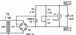
Original Mr Pass are verified and simple , work like a charm :
two resistors, two caps, trimer and TL431 50w Single-Ended BAF2015 Schade Enabled
One more complicated news : I don't see benefits of " innovation" with 20 resistors in CCS ,
four resistors for two channels is show in original schematic 🙂 Best regards
two resistors, two caps, trimer and TL431 50w Single-Ended BAF2015 Schade Enabled
One more complicated news : I don't see benefits of " innovation" with 20 resistors in CCS ,
four resistors for two channels is show in original schematic 🙂 Best regards
The same bias circuit was in the past a work horse for all DIY Vfet's amplifiers.
Edit:
New useful trick is the use of two parallel output capacitors instead of one 10 000 uF
at the Schade 50 Watt's outputs and his SIT Tokin version.
Learning lesson from F8

Edit:
New useful trick is the use of two parallel output capacitors instead of one 10 000 uF
at the Schade 50 Watt's outputs and his SIT Tokin version.
Learning lesson from F8
Attachments

- Home
- Amplifiers
- Pass Labs
- 50w Single-Ended BAF2015 Schade Enabled