The circuit is perfect but my implementation has some sort of flaw. Thanks to the incredible support from the forum we'll eventually get to the bottom of this!
Regards,
Dan 😀
P.S. More tests, trials, and tribulations soon!
Regards,
Dan 😀
P.S. More tests, trials, and tribulations soon!
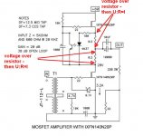
Build from original Mr Pass schematics and avoid another " genius innovator "
make life simple 😉
make life simple 😉
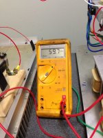
Back to some basic testing before I try ZMs suggestions. Seen below is my rail voltage and my CCS happily supplying my 4R0 test resistor with 3.2 amps.
Regards,
Dan 🙂


Regards,
Dan 🙂
Attachments
Last edited:
A suggestion if you are going to test the lower circuit:
Do not measure current with a meter in series in the circuit. Measure the voltage drop across the 0.2R and convert to Ampere. All of your previous fried CCS Mosfets have occurred with the Ammeter in series and then removed. Time to try something different.
When I fired up my amp for the first time, I used a dim bulb tester with a 250W bulb. I made sure that the lower circuit was drawing some current with no problems. Then I powered down, removed the dim bulb tester, let the thermistors cool, and then powered up again and further adjusted Vbias to get to the proper Vds of the lower stage.
A suggestion if you are going to test the lower circuit:
Do not measure current with a meter in series in the circuit. Measure the voltage drop across the 0.2R and convert to Ampere. All of your previous fried CCS Mosfets have occurred with the Ammeter in series and then removed. Time to try something different.
When I fired up my amp for the first time, I used a dim bulb tester with a 250W bulb. I made sure that the lower circuit was drawing some current with no problems. Then I powered down, removed the dim bulb tester, let the thermistors cool, and then powered up again and further adjusted Vbias to get to the proper Vds of the lower stage.
Am I safe assuming once a CCS is ‘set’ to deliver 3.2 amps to the test resistor that it will deliver that same 3.2 amps to the lower mosfet? My ammeter seems to indicate that is the case when in series with the entire circuit.
The last time I adjusted bias I did so to reach a target current (3.2A). After I did that I measured Vds and it was 27.6vdc.
I am going to try two different things when time permits. I’m going to install ZMs zener/cap suggestion on the CCS and I’m going to
use an external ps to feed the greenie bias circuit.
Regards,
Dan
Last edited:
It should if it is functioning properly. It is a "Constant Current Source".
When you set the lower Mosfet operating point, you should be adjusting for Vds, not for current. The goal is to set Vds to 28V. You can monitor the current by measuring the voltage drop across the 0.2R (0.64V). If the current starts to go above 3.2A that you had set the CCS at, then there is something wrong.
When you set the lower Mosfet operating point, you should be adjusting for Vds, not for current. The goal is to set Vds to 28V. You can monitor the current by measuring the voltage drop across the 0.2R (0.64V). If the current starts to go above 3.2A that you had set the CCS at, then there is something wrong.
It depends on how your lower MOSFET is biased. The less it conducts, the lower the voltage drop in your CCS resistors, so the upper Vds will be higher while the lower Vds will be less.
Edit: the node voltage between upper and lower should be higher, not the upper Vds
Edit: the node voltage between upper and lower should be higher, not the upper Vds
Last edited:
when you are in ballpark, with iterative settings of two trimpots (one in CCS, second bias of lower mosfet) you're fine-tuning both Iq and output node voltage potential
what is not clear enough - is id you had some massive oscillation in Mu part of amp
if you mounted protection zenner and that G-D cap, you're preventing in good amount possible BadaBoom of Mu mosfet
even if Mu Iq is pre-set just roughly, if you start with 0V of biasing voltage for lower mosfet, gradual setting procedure should be safe; voltage across lower mosfet starts from huge, decreasing as you open it more, while Iq is rising...... while voltage across uper mofet starts from low, increasing with gradual opening of lower mosfet, same as Iq
if you connected everything by the book, you really don't need pre-set of Mu Iq...... all you need is just verification that biasing voltage for lower one is starting from 0V
Back to some basic testing..
Anyways, they do not make heatsinks heavier and bigger
with a potential to dissipate a lot of heat especially in the summer season

Heat sinks performance is better in vertical stand up position

50W-SE-Schade - measurements
I fully agree with Ben (#1445) and also with pinholer (#1447).
I measure the current = voltage over the 0.2 Ohm resistors (I have used 4 of 0.1 Ohm).
I also made the same experience like pinholer - depending on the bias of the CCS- mosfet you can get a big 'inbalance' of voltage between the upper and the lower MosFet. 🙄
And I also made the protection - zenerdiodes onto the gates of the IXYS-Mosfets.
Greets
Dirk
Attachments

Anyways, they do not make heatsinks heavier and bigger
with a potential to dissipate a lot of heat especially in the summer season
Heat sinks performance is better in vertical stand up position
I leave the heat sinks flat for short term tests before too much heat is built up. For the real tests they are vertical with fans on standby if needed. 😱
Regards,
Dan
Back to some basic testing before I try ZMs suggestions. Seen below is my rail voltage and my CCS happily supplying my 4R0 test resistor with 3.2 amps.
Regards,
Dan 🙂
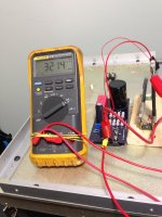
Just for fun here. In resistor test mode. Vds is 41.7Vdc and Vgs is 4.04Vdc.
Regards,
Dan

Ben (post 1445) is right on. I learned the hard way although I didn't realize the lesson until later.
I now only measure voltage drops and as Dirk says compute current.
Best
Bob
I now only measure voltage drops and as Dirk says compute current.
Best
Bob
Ben (post 1445) is right on. I learned the hard way although I didn't realize the lesson until later.
I now only measure voltage drops and as Dirk says compute current.
Best
Bob
I tried your suggestion but the numbers were a bit off.
Calculated R with the eight resistors is .407 Ohms.
Measured voltage drop of 1.370V/.407R gives a higher calculated current (3.366A)
than was being measured 3.250A. I suppose 100mA is an acceptable error.
I dare to say my CCS is functional and doesn't differ from Pa's original design in any meaningful way.
Regards,
Dan
Last edited:
Dan
Can you measure the resistance?
Just curious if that would give the same current.
Best
Bob
Can you measure the resistance?
Just curious if that would give the same current.
Best
Bob
Dan
Can you measure the resistance?
Just curious if that would give the same current.
Best
Bob
Your regular Fluke meters cannot measure sub one ohm accurately.
Regards,
Dan
Dan
I wasn't sure what meters you had.
3% difference would be OK with me - but that's me.
Best
Bob
I wasn't sure what meters you had.
3% difference would be OK with me - but that's me.
Best
Bob
I just made some measurements on my THF-51S amp. The current does vary slightly with Vds.
Vds=37.3V Iq=2.26A
Vds=30.6V Iq=2.37A
Iq was measured across 0.1R
So the current does does move a bit. As Zen Mod said earlier, the current can be fine tuned with the pot in the CCS. My CCS does not have a pot so no adjustment for me, but such as small variation in current does not bother me.
Vds=37.3V Iq=2.26A
Vds=30.6V Iq=2.37A
Iq was measured across 0.1R
So the current does does move a bit. As Zen Mod said earlier, the current can be fine tuned with the pot in the CCS. My CCS does not have a pot so no adjustment for me, but such as small variation in current does not bother me.
when you are in ballpark, with iterative settings of two trimpots (one in CCS, second bias of lower mosfet) you're fine-tuning both Iq and output node voltage potential
what is not clear enough - is id you had some massive oscillation in Mu part of amp
if you mounted protection zenner and that G-D cap, you're preventing in good amount possible BadaBoom of Mu mosfet
even if Mu Iq is pre-set just roughly, if you start with 0V of biasing voltage for lower mosfet, gradual setting procedure should be safe; voltage across lower mosfet starts from huge, decreasing as you open it more, while Iq is rising...... while voltage across uper mofet starts from low, increasing with gradual opening of lower mosfet, same as Iq
if you connected everything by the book, you really don't need pre-set of Mu Iq...... all you need is just verification that biasing voltage for lower one is starting from 0V
Installed Zener, Cap, and 4A line fuse. Didn't seem to like the cap. It wouldn't 'turn on' till I took the cap off.
One odd thing. I setup my usual test circuit with the CCS feeding the 4R0 resistor and drawing 3.2A. I jumpered out the ammeter and current immediately goes down to about 400mA. 😕
So in this particular setup the meter is a 'load' or 'resistance' as seen by the circuit.
Regards,
Dan
Last edited:
- Home
- Amplifiers
- Pass Labs
- 50w Single-Ended BAF2015 Schade Enabled