it was working, while proper temp?
at which temp it gone south?
The heatsink was getting so hot it failed the touch test. Two mosfets have failed now, shorted D to S, etc. It will cost very little to set up some fans to give me a greater margin of safety while I do more testing.
If your going to run with the big boys (massive kilowatts) you better to be ready for a few bumps and bruises. 😉
they are Biguns, but still needing sane temp while dealing with DC juice
having your sinks sitting on bench without clearance isn't helping
having your sinks sitting on bench without clearance isn't helping
they are Biguns, but still needing sane temp while dealing with DC juice
There may be more to the story but only testing will give the answers. Fans are cheap as well as a portable PS. Once I have those in place I'll do more testing and have more answers.
Regards,
Dan
to Dantworney
Hello Dan,
remember my post #1342 ?
It will get hot! Especially at a bias around 3.2 - 3.4 amps. The IXYS are monsters!
I have a 8U high heatsink - and it gets toasty hot!


If it is hot - check for runaway of your bias....
Greets
Dirk 😀
Hello Dan,
remember my post #1342 ?
It will get hot! Especially at a bias around 3.2 - 3.4 amps. The IXYS are monsters!
I have a 8U high heatsink - and it gets toasty hot!
If it is hot - check for runaway of your bias....
Greets
Dirk 😀
Hello Dan,
remember my post #1342 ?
It will get hot! Especially at a bias around 3.2 - 3.4 amps. The IXYS are monsters!
I have a 8U high heatsink - and it gets toasty hot!
If it is hot - check for runaway of your bias....
Greets
Dirk 😀
The CCS is getting super hot and eating MOSFETs. Fans are going to be a short term solution to get me through testing and perhaps some sort of protection like https://www.mouser.ca/ProductDetail/Sensata-Technologies/1NT01L-7937?qs=F5EMLAvA7IDvFVHB4Yonlw%3D%3D
Regards,
Dan
one day, when I grow up and find some time - to make my own Singing Bush, I'm going to use 3 sinks connected together, each one capable for 100W of heat, fanless
I resume they're going to be enough for 190W of heat per channel
I resume they're going to be enough for 190W of heat per channel
If memory serves.........Father Pass used an 85C thermal switch in his Alephs?
🙄
Regards,
Dan
🙄
Regards,
Dan
Dirk gave me something interesting to think about...................
😉
Regards,
Dan
Power MOSFET thermal runaway. The on-resistance of a power MOSFET increases with temperature. With the resistance increase, the power dissipated for a constant on-current increases, the junction temperature increases, and the resistance further increases until the device is in thermal equilibrium with the heat removal system. If the heat removal system is inadequate, thermal run away occurs.
😉
Regards,
Dan
Papa's amp in question didn't had biasing circuit taking ace of thermal runaway ( now my Singing Bush is having), simply accounting on hefty chunk of Aluminum
I mean - heeeeeefty
including anti-thermal runaway biasing circ would complicate things, while having amp with decreasing Iq is counterproductive per se
conclusion - heeeeeefty is Conditio Sine Qua Non, as with any Papamp
either that , or hefty with additional Rotating Blades
I mean - heeeeeefty
including anti-thermal runaway biasing circ would complicate things, while having amp with decreasing Iq is counterproductive per se
conclusion - heeeeeefty is Conditio Sine Qua Non, as with any Papamp
either that , or hefty with additional Rotating Blades
Papa's amp in question didn't had biasing circuit taking ace of thermal runaway ( now my Singing Bush is having), simply accounting on hefty chunk of Aluminum
I mean - heeeeeefty
including anti-thermal runaway biasing circ would complicate things, while having amp with decreasing Iq is counterproductive per se
conclusion - heeeeeefty is Conditio Sine Qua Non, as with any Papamp
either that , or hefty with additional Rotating Blades
Didn't Pa once say get the biggest heatsinks you can and then double it? 😉
Fans and thermal switches are on the way. That 'should' lessen future MOSFET sales?
Regards,
Dan

Papa's amp in question didn't had biasing circuit taking ace of thermal runaway ( now my Singing Bush is having), simply accounting on hefty chunk of Aluminum
......
that meant to be :
Papa's amp in question didn't had biasing circuit taking care of thermal runaway ( nor my Singing Bush is having), simply accounting on hefty chunk of Aluminum
but my fingers are sometimes even more dyslexic than usual .....

Good evening to all of you.
I’m about to finalize my amp but I have a few questions to ask before powering on:
-do I need to connect the input ( point 1 of the transformer JT-123-FLPCH ) to the GND to make the adjustments?
-Does the speaker need to be connected to the less of the capacitor (10000µF/80V) and the return of the speaker to GND?
Good evening to all of you.
I’m about to finalize my amp but I have a few questions to ask before powering on:
-do I need to connect the input ( point 1 of the transformer JT-123-FLPCH ) to the GND to make the adjustments?
-Does the speaker need to be connected to the less of the capacitor (10000µF/80V) and the return of the speaker to GND?
I would say it's highly advisable to put the + input to ground for adjustment. Speaker does not need to be connected.
Please be patient here because this is going to take several post and lots of pictures and drawings to explain my issue. 🙂
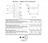
First the power supplies. First I am using two 800VA Antek 8445's as the toroids here. Here's their drawing.

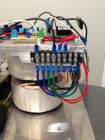
Here's a pic of the terminal strip for the secondaries. Each toroid has their own separate one.

With the wires detached in the picture both toroids produced the correct secondary voltages (49VAC, 19VAC, and 13VAC). As you can see the Blue/Greens are paralleled to feed each bridge rectifier.
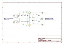
Here's a schematic of my main PS.

As you can see the two negatives are tied together and then tied to chassis ground through the standard CL60 thermistor.
You can see the ground terminal strip and the thermistor is this pic.

Next is the +/-12VDC supply I need for my input buffers. Here's the schematic.

The bipolar supply here takes it's 13VAC, one from each toroid's set of orange wires, as you can see in the pic of the terminal strip. Also, you can see that the ground (J4) is tied to the ground of the main PS.
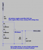
And last but not least the Great ZM's bias circuit I'm using.

Both separate bias circuits take their supply from the +12VDC side of the regulated bipolar supply.
So in closing of Part 1 of this post I'd like to point out that ZM's bias circuit produces a perfect and accurate range of voltages for the bias.
Also, the bipolar supply works perfectly producing a +/-12VDC.
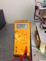
And finally, the main supply produces 65VDC unloaded as seen here.

Regards,
Dan
First the power supplies. First I am using two 800VA Antek 8445's as the toroids here. Here's their drawing.
Here's a pic of the terminal strip for the secondaries. Each toroid has their own separate one.
With the wires detached in the picture both toroids produced the correct secondary voltages (49VAC, 19VAC, and 13VAC). As you can see the Blue/Greens are paralleled to feed each bridge rectifier.
Here's a schematic of my main PS.
As you can see the two negatives are tied together and then tied to chassis ground through the standard CL60 thermistor.
You can see the ground terminal strip and the thermistor is this pic.
Next is the +/-12VDC supply I need for my input buffers. Here's the schematic.
The bipolar supply here takes it's 13VAC, one from each toroid's set of orange wires, as you can see in the pic of the terminal strip. Also, you can see that the ground (J4) is tied to the ground of the main PS.
And last but not least the Great ZM's bias circuit I'm using.
Both separate bias circuits take their supply from the +12VDC side of the regulated bipolar supply.
So in closing of Part 1 of this post I'd like to point out that ZM's bias circuit produces a perfect and accurate range of voltages for the bias.
Also, the bipolar supply works perfectly producing a +/-12VDC.
And finally, the main supply produces 65VDC unloaded as seen here.
Regards,
Dan
Attachments
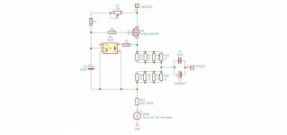
Part 2
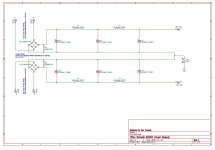
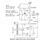
If you refer to the original drawing here.

You'll see where I've taken the top half and created my own CCS.

Next is a schematic of my CCS test circuit. The main power supply feeds the 'D' screw with the 60VDC and I take the output of the CCS to a 4R0 500W resistor then through my Fluke meter to ground. This test setup works perfectly with the pot adjusting current within a reasonable range. I adjust the CCS to produce 3.2 amps DC through this resistor.

Regards,
Dan
If you refer to the original drawing here.
You'll see where I've taken the top half and created my own CCS.
Next is a schematic of my CCS test circuit. The main power supply feeds the 'D' screw with the 60VDC and I take the output of the CCS to a 4R0 500W resistor then through my Fluke meter to ground. This test setup works perfectly with the pot adjusting current within a reasonable range. I adjust the CCS to produce 3.2 amps DC through this resistor.
Regards,
Dan
Attachments
Last edited:
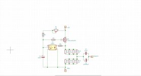
Part 3
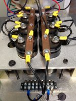
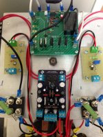
I now add the bottom half of the circuit as seen here with my Fluke meter in series to measure the current through the circuit. I adjust the bias voltage to get very close to 3.2A DC through this circuit. ZM's bias circuit seems to work perfectly adjusting the current up and down at will. The CCS is now perfectly feeding this circuit with no issues other than a little heat!

Regards,
Dan
I now add the bottom half of the circuit as seen here with my Fluke meter in series to measure the current through the circuit. I adjust the bias voltage to get very close to 3.2A DC through this circuit. ZM's bias circuit seems to work perfectly adjusting the current up and down at will. The CCS is now perfectly feeding this circuit with no issues other than a little heat!
Regards,
Dan
Attachments
Last edited:
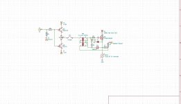
Part 4
Now the scary part that I've been through three times already. I get the entire circuit up and running as far as I know as it was designed to do. I get the CSS half to produce a perfect 3.2A through a test resistor before I feed the bottom half of the circuit. I connect the bottom half of the circuit to the CCS and use the bias to carefully adjust the current through the second MOSFET to the desired 3.2A. Everything looks perfect. Both MOSFETs are producing heat and all voltages check out.
Then disaster strikes. As soon as I remove the ammeter from the circuit and attach it directly to ground it instantly eats the CCS MOSFET.
Design flaw or defect? So far I'm scratching my head! 😕
Regards,
Dan
- Home
- Amplifiers
- Pass Labs
- 50w Single-Ended BAF2015 Schade Enabled