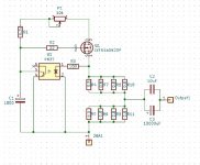
The only thing I'm questioning is why the 6.8K resistor across both D-S? I recall earlier in this thread about putting 220R across the lower D-S to stabilize the bias, and possibly the upper if needed. I would say just remove those. Did R3 burn up on startup?
The only thing I'm questioning is why the 6.8K resistor across both D-S? I recall earlier in this thread about putting 220R across the lower D-S to stabilize the bias, and possibly the upper if needed. I would say just remove those. Did R3 burn up on startup?
R3 burned on startup. The 6.8K are bleed down resistors on the power supply.
The road to success is paved with...................😱
I have a specific plan.
Lots of details and porn later..............🙂
Regards,
Dan
just realized I was looking at a previous pic of your bridges...oops. Maybe ditch that soft start and starup with a variac....? I startup with a 12R resistor on L1 mains, then use another switch after about 5 seconds to cut the resistor out and get full rails. Even then it takes about 15-20 seconds for the opto-coupler to 'wake-up'...maybe that SLB soft start you got there is playing havoc with it..?
Last edited:
just realized I was looking at a previous pic of your bridges...oops. Maybe ditch that soft start and starup with a variac....? I startup with a 12R resistor on L1 mains, then use another switch after about 5 seconds to cut the resistor out and get full rails. Even then it takes about 15-20 seconds for the opto-coupler to 'wake-up'...maybe that SLB soft start you got there is playing havoc with it..?
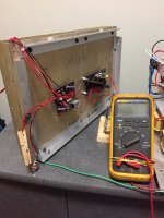
Here's my initial plan with heatsink separated from chassis and current being monitored. This has work perfectly before with the correct bias.
Test surviving CSS with the 4 ohm 500watt resistor as load. This has worked very well in previous tests.
If that passes then hook it up to the bottom half of the circuit and test again.
If that passes I'm going to re-install in the chassis and using my variac to bring it up slow and watch for smoke. No smoke means next step is a full voltage test.
Lots of details and porn when time permits.
Regards,
Dan
P.S. Remember. The road to success is strewn with burnt components of all shapes and sizes?
 😀
😀If it had worked with the heat sink separated from the chassis but drew current to burn resistors with the heat sink attached to the chassis, perhaps there is something shorting to the heat sink but not causing problems when the heat sink is not grounded but becomes a problem when there is a path to ground through the chassis to ground.
If it had worked with the heat sink separated from the chassis but drew current to burn resistors with the heat sink attached to the chassis, perhaps there is something shorting to the heat sink but not causing problems when the heat sink is not grounded but becomes a problem when there is a path to ground through the chassis to ground.
An excellent point that has been on my mind since my TL431’s started smoking for no reason.
I’m going to take a reasoned and methodical approach that will hopefully prove or disprove your theory. If everything works flawlessly with the heaksink separated I’m going to be very cautious after that!
Regards,
Dan
If it had worked with the heat sink separated from the chassis but drew current to burn resistors with the heat sink attached to the chassis, perhaps there is something shorting to the heat sink but not causing problems when the heat sink is not grounded but becomes a problem when there is a path to ground through the chassis to ground.
You got me thinking.............

I suppose a ground is just a piece of wire with an alligator clip on each end? 😉
That’ll be one of my final tests!
Regards,
Dan
Use your meter with one probe on the heat sink and then use the other probe to check various parts of your circuit for continuity to the heat sink. There should be no continuity. Also look to see that there are no parts or stray wires or leads from the boards touching the heat sink. Check your standoffs are not shorting to the boards too.
Ben gave you (as always) some clever and reasonable tips
whenever I'm trying exactly that, result is major Ookup; dunno, most likely illustration of state of my reason

......
I’m going to take a reasoned and methodical approach ........
whenever I'm trying exactly that, result is major Ookup; dunno, most likely illustration of state of my reason
Ben gave you (as always) some clever and reasonable tips
whenever I'm trying exactly that, result is major Ookup; dunno, most likely illustration of state of my reason
It's too bad I just retired my 10kv megger. It was great for finding grounds! 😉
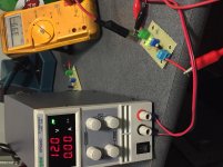
Step #1 One dead mosfet. Which came first. The chicken or the egg?
Surviving CCS board and a different mosfet and all is well with the 4 ohm resistor at 3.3 amps.
Regards,
Dan 🙄
Surviving CCS board and a different mosfet and all is well with the 4 ohm resistor at 3.3 amps.
Regards,
Dan 🙄
Last edited:
I believe ( and hope) your dilemma will end as easier that that one
Order two dozen green LEDs and a dozen MOSFETs? 😱
Regards,
Dan
does egzzzz always goes in dozens?
try finding what you ooked up, when assembling da amp in whole
circuit is well proven and it's certainly better that's the case and you made a mistake, then the other way around
does egzzzz always goes in dozens?
try finding what you ooked up, when assembling da amp in whole
circuit is well proven and it's certainly better that's the case and you made a mistake, then the other way around
NO worries. One little step at a time. 😉
Regards,
Dan
- Home
- Amplifiers
- Pass Labs
- 50w Single-Ended BAF2015 Schade Enabled