Hi baudouin0,
If you have read the links I've suggested you, and gingertubes impressions on this forum, you will find the reason why I want (especially with an instrument like bass) to use them. It would be a downgrade to come back to resistors.I am not suggesting removing the mosfet's that is a necessary thing just the 6xCCS that go with it.
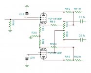
Yes, it is already there as in the schematic I've drawn and attached to the first post of the thread (even if it was a 12ax7 and not an EF86).Just be aware that if you go for a pentode splitter you may need a balance pot.
Last edited:
To avois any possibility to be in contact with 900 Vdc even if the OT fails. Thanks!
Roberto, maybe I should have put it somewhat clearer. There ain't no shield windings in my OT, which, due to the interleaves, would have been some tedoius task. The speaker windings are grounded here anyway.
I've ordered (and finally received...) it between the primaries (2 x 115 Vac) and the secondaries of my power tranny. So it either helps to minimize RFI from the power grid and also yields protection if the PT should fail. I just don't want to get electrocuted when playing my bass guitar and touching the mike or anyting else that is grounded simultaneously 😉.
Remember Keith Relf, former member/guitarist with The Yardbirds and Renaissance, who died in 1976 due to such an incident (I tend to suspect that he used a PT less, live chassis amp, though).
Best regards!
baudouin0, two remarks to your schematics:
1st: I suspect V4 as a negative (-70 Vdc) voltage source is drawn upside down.
2nd: Assuming you're feeding the LTP tail with -70 Vdc, are you sure that a BC846 will stand it? What's the expected cathode voltage of both pentodes?
Best regards!
V4 is OK are voltage is shown as -70 not 70 so that's correct. Your quite correct I'am not using a BC846 in the real design its a MPSA42 from memory. The voltage rating is not critical to the simulation.
I will leave you to your 83 post of skilled persons and wish you the best of luck with your project.
Thanks Kay, well receipt now.I've ordered (and finally received...) it between the primaries (2 x 115 Vac) and the secondaries of my power tranny. So it either helps to minimize RFI from the power grid and also yields protection if the PT should fail.
I've sketched the schematic in two options, but I would like to do it better, in the meanwhile I add some calculations:
Let's use your data Kay:
900 V and 30 mA at ide, 8k1 Raa (per pair, that's 2k7 per sextet), g2 at 270 V and g3 at +30 V it should have g1 at around -43 V.
Class AB1:
GU50s will swing from 900 down to approximately 160 V when g1 will go from -43 up to 0 V. That's a gain of 17, (that's also the same as the Baby Huey).
A possible solution could be the one attached here for the PI:
430 V and 4,8 mA at idle, 47k Ra, g1 at 1,5 V, g2 at 140 V.
To reach that voltage at idle, starting from 900 V of the plates, it would be needed to have:
(900 V - 430 V) / 4,8 mA = 97, 92 kOhm
Within the 100 kOhm 5% tolerance, so shunt feedback network could be 100 kOhm and 33 kOhm inbetween (just doubled the values used on the BH to keep the same ratio).
The shunt voltage divider is 16,5 / 116,5 = 1 / 7.
So on the hypotetycal 47 kOhm there will be 17 / 7 = 2,5 times the signal on g1(GU50) = a(EF86).
The anode of the phase inverter sees (47 kOhm + (100 kOhm // 16,5 kOhm)) / (2,5 + 1) = 17,5 kOhm and the 1 MOhm (bias reference) in parallel. So a total dynamic load of 17,2 kOhm.
As Kay was saying me pages ago ( 450W bass amp: a sextet of GU50s with shunt¤t feedback ) EF86 is too whimpy.
Anyone has experience with compactron dual pentodes on noval socket?
I wouldn't suggest feeding the PI tubes from the output plates when the latter work on 900 Vdc, 'cause there aren't many that cope with that voltage. I don't know of any small signal pentode that will do. Maybe a frame deflection output pentode can.
OTOH I guess a high transconductance pentode that can carry significant plate current might do when fed from about 400 Vdc. That's why I suggested something like EF80 or EF184 previously.
Best regards!
Edit: The only double pentode in a Noval (B9) envelope that I know is the ELL80 - two EL95's in one bottle. Scarce and expensive today!
So to keep the same feedback configuration it is needd to split the BH 16k resistor into two of 8k, and connect that point to the voltage supply, then connect the plates to the BH 47k resistors through a 1 uF capacitor.I wouldn't suggest feeding the PI tubes from the output plates when the latter work on 900 Vdc, 'cause there aren't many that cope with that voltage.
I will search some if available.I don't know of any small signal pentode that will do. Maybe a frame deflection output pentode can.
OTOH I guess a high transconductance pentode that can carry significant plate current might do when fed from about 400 Vdc. That's why I suggested something like EF80 or EF184 previously.
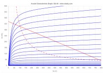
I've found here ( www.wavebourn.com • View topic - Gubernator - 71 single ended amplifier ) the 12HL7 that seems very linear:
http://www.r-type.org/pdfs/12hl7.pdf
Seems more similar to EF184 than EF80, but more linear than them:
http://www.r-type.org/pdfs/ef80.pdf
http://www.r-type.org/pdfs/ef184.pdf
Last edited:
Another option could be the 6Z49P-DR or 6J49P-DR:
6Z49P-DR/6J49P-DR Pentode – Bartola(R) Valves
6Ж49П-ДPУ / 6Z49P-DRU [triode] | VT52.com
This is in triode mode:
http://vt52.com/sites/default/files/2018-07/curve 6Z49P_triode.jpg
Here there's a list of other candidates:
Driving hard (Part I) – Bartola(R) Valves
6Z49P-DR/6J49P-DR Pentode – Bartola(R) Valves
6Ж49П-ДPУ / 6Z49P-DRU [triode] | VT52.com
This is in triode mode:
http://vt52.com/sites/default/files/2018-07/curve 6Z49P_triode.jpg
Here there's a list of other candidates:
Driving hard (Part I) – Bartola(R) Valves
I will present in this post my favourite contenders for the best drivers. These are:
6e6p-dr: the brother of the famous 6e5p, but a real performer on his own
6z49p-dr: an amazing pentode.
6z52p: high-gm and mu pentode. A replacement for the E810F or D3a for some. This is a pentode that works brilliantly on all fronts. Even at low voltages (thanks JC Labs)
6C45p: this little triode monkey oscillates widely, but can be tamed and works well, so don’t be afraid.
6e5p: this famous Russian beauty doesn’t need introduction
12HL7: the sleeper and best discovery last year.
I will split the power supply's 900 V in three windings in series, in order to use 450V rated capacitors for each one.I wouldn't suggest feeding the PI tubes from the output plates when the latter work on 900 Vdc, 'cause there aren't many that cope with that voltage.
Could be a solution to directly connect the plates of the GU50s and the ones of the drivers, and then connect the CCS of the PI to the 300V? This will reduce the voltage seen by the PI and extend the number of possible pentodes.
It will be needed a coupling cap for the NFB (no problem) and elevate the heaters with a dedicated winding (I don't like it).
Last edited:
So to keep the same feedback configuration it is needd to split the BH 16k resistor into two of 8k, and connect that point to the voltage supply, then connect the plates to the BH 47k resistors through a 1 uF capacitor.
I'm not sure what you're intending really. But if you want bootstrapping, you'll need to split the 16 k into two 33 k ones to keep DC load resistance the same.
Best regards!
I will resume some points here, trying to use 12HL7 as a driver.
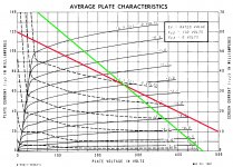
Attached the loadline of the GU50 with 900 V B+ 30 mA at idle, 8k1 Raa, -43 V g1, 270 V g2, 30 V g3.
So as written before:
Class AB1:
GU50s will swing from 900 down to approximately 160 V when g1 will go from -43 up to 0 V. That's a gain of 17, (that's also the same as the Baby Huey).
The shunt feedback total resistance must be at least 10 times GU50's Raa in order not to interfere with them (and not to waste power through them), so at least 27 kOhm.
Considering the same 47 kOhm and 16 kOhm ratio, it could go down to 12 kOhm and 3,9 kOhm.
A reasonable working point for the 12HL7 is something less than 70 mA, so the voltage drop across the shunt feedback resistor would become 840 V.
Again not possible.
It seems that the only way is to decouple the shunt feedback signal through a capacitor and feeding into the PI. The easierst way to do it seems to me to split the plate load of the PI into two resistors, and connect the capacitor there.
The PI will have a dedicated and lower B+.
Attachments
To design the driver , you must designate the Schade feedback ratio first. As you don't have overall NFB , the ratio should be very high , particularly the positive feedback will increase the distortion. I use 75% in this application Extra power,higher DF,lower distortion from SE pentodes , and I am not fully satisfied. I advise you to start with 50% , although Schade uses 10% without explaining why. Than on simulator you can refine the ratio. With 75% I simulated push pull version, at saturation it goes into oscilation.
Kay is already suggesting me to implement some global NFB together with shunt/Shade and current feedback. I just would like to understand and learn how to do it before going into simulation.To design the driver, you must designate the Schade feedback ratio first.I advise you to start with 50%
Thank for the link, but I'm sorry it's not clear to me how this can be implemented here.
Let me sketch what I have in mind and see if it can work.I'm not sure what you're intending really. But if you want bootstrapping, you'll need to split the 16 k into two 33 k ones to keep DC load resistance the same.
Roberto, honestly I wouldn't think about Schade at all in a musical instrument amplifier. You surely don't need high fidelity here, not even in an amp for the bass guitar. In contrary, some minor distortion will enhance the overall sound.
Best regards!
Best regards!
Thanks Kay, I know tube power amps for instrument amplification are not there to sound clean as an HiFi, but I have to say I don’t like too much power amp distortion for bass (while I do for guitar) and for the ones I’ve built I always went for Class D with SMPS power supply.
That’s why I would go this way.
That’s why I would go this way.
smoking-amp kindly suggested me the 6GF5 vertical deflection output pentode, which curves are apparently same as 6GE6: http://www.r-type.org/pdfs/6ge5.pdf
I'm searching a way to linearize it.
I'm searching a way to linearize it.
Hi kokoriantz,
I've searched your schematic, and I've found this variation:
does the 3A5 have the stones to drive a 2A3?
The Shunt Cascode Driver – Bartola(R) Valves
and its (quite more complicated) developement for a push pull here:
What’s on the bench – wauwatosa tube factory
with a dedicated pcb here:
Rod Coleman Shunt Cascode - Power Tube Driver
Here an explanation of the circuit:
Pentode driver with gyrator load – Bartola(R) Valves
The circuit can be explained easily. The pentode (U1) is loaded with the gyrator (g1). The pentode screen has a stable voltage (vs) which is provided by the voltage regulator (U2) and the CCS formed by M1+R2. You can implement the screen voltage source that best suits you. Anyhow, the input is provided to the grid (g1) and the grid resistor (Rg) provides ground reference. The cathode resistor (Rk) is un-bypassed. Quite unusual for a pentode. The thing is, we have gain to spare, but thanks to the gyrator, the output impedance of the stage isn’t mu times the Rk. Hence we can afford adding this resistor which also linearise the stage thanks to the negative feedback introduced. Ra is required to provide a stable output and limit the gain. The gain is therefore Gm times the Ra, Gm is degenerated due to Rk (unless you bypass it).
- Home
- Amplifiers
- Tubes / Valves
- 450W bass amp: a sextet of GU50s with shunt¤t feedback