I see this topology the best. R11&R12 need to be paralleled with capacitors.The precedent is only to show 75% is possible. It is to note that 50% feedback ratio is also the case for unity coupled and circlotron.
Last edited:
Why should a filter resistor R11 and a grid leak R12 be bypassed with capacitors?
Best regards!
Best regards!
R11&R12 in my proposed topology, are feedback resistors from the output plates. They are intended to decrease the dc 1kv at start up to acceptable level for the driver , but the capacitors maintain the ac voltage . You are confusing with the RCA circuit .
Last edited:
You're referring to which schematics, please? I was referring to the last one you've posted 🙄.
Best regards!
Best regards!
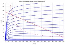
Hi, I've played a bit with the EF86 pushing it to its limits.
In attachment you can find the loadlines.
GU50 as before: B+ 900 V, Ia 30 mA, g1 -43 V, g2 270 V, g3 30 V, Raa 8k1
EF86 B+ 550 V, Ia 5,1 mA, g1 -2,4 V, g2 180 V, Ra 68k shunt 12k & 3k3.
This way the EF86 can drive the GU50s into AB2... but... I still need to drop (900-550) = 450 V that must be constant even when varying the current.
Attachments
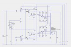
Do you like the transistor driver stage?
I am collecting parts for a GU-50 pp amp using 7193 (l,r) and 2C34 (l+r). Have no idea what it will sound like.
I am collecting parts for a GU-50 pp amp using 7193 (l,r) and 2C34 (l+r). Have no idea what it will sound like.
Thanks brightcity, your configuration is a triode to split the signal, then a second triode for each side of the split signal? I excluded that configuration as I would like to keep it straight phase inverter then mosfet drivers to have the ability to bring output tubes into AB2.
I still need to drop (900-550) = 450 V that must be constant even when varying the current.
You can half the voltage easily connecting two same size electrolytes in series together with two parallel resistors. If the anode current drops this divided voltage too much perhaps connecting a diode in series with the top electrolyte prevents anode current run from the bottom capacitor and preamp voltage stay better stable. I haven't tried this diode method but it should work?
If you need other than just the half voltage using two different size capacitors is possible and how the voltage form follow simple math which is presented in various web pages.
Esa
Ciao 2L man,
I need the AC component to stay fixed, while the DC component is reduced by 450V independently from the current flowing through that added component.
Your solution doesn't accomplish those things.
I need the AC component to stay fixed, while the DC component is reduced by 450V independently from the current flowing through that added component.
Your solution doesn't accomplish those things.
Hi,
before posting the updated schematic I'll explain it here: looking at the BHEL84 configuration with 220k on plates of the 12AX7, then 47k to the plates of EL84 and 16k in between, if I add two CCS at the two extremes of the 16k to ground, I have an (almost) infinite impedance AC, and a constant voltage drop (the constant current source multiplied by the 47 kOhm, in that case).
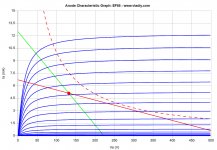
I've also drawn the loadlines of the GU50s for 20% (for instrument amplification version) and 43% (for Hi-Fi) UL connections.
before posting the updated schematic I'll explain it here: looking at the BHEL84 configuration with 220k on plates of the 12AX7, then 47k to the plates of EL84 and 16k in between, if I add two CCS at the two extremes of the 16k to ground, I have an (almost) infinite impedance AC, and a constant voltage drop (the constant current source multiplied by the 47 kOhm, in that case).
I've also drawn the loadlines of the GU50s for 20% (for instrument amplification version) and 43% (for Hi-Fi) UL connections.
Edit: It is 85 Vp, not Vpp. So 60 Vrms.
That is acceptable for an instrument bass amplifier.
I will try to modify it to adapt for Hi-Fi purposes as well.
Any suggestion on how to improve it?
Code:
Harmonic	Frequency	 Fourier 	Normalized	 Phase  	Normalized
 Number 	  [Hz]   	Component	 Component	[degree]	Phase [deg]
    1   	1.000e+03	8.368e+01	1.000e+00	   -1.01°	    0.00°
    2   	2.000e+03	2.782e-02	3.325e-04	 -103.61°	 -102.60°
    3   	3.000e+03	8.426e-01	1.007e-02	   89.62°	   90.63°
    4   	4.000e+03	3.521e-02	4.208e-04	 -111.50°	 -110.49°
    5   	5.000e+03	3.849e-01	4.599e-03	  135.74°	  136.75°
    6   	6.000e+03	1.908e-02	2.280e-04	   68.71°	   69.72°
    7   	7.000e+03	1.739e-01	2.078e-03	  121.08°	  122.09°
    8   	8.000e+03	5.035e-03	6.017e-05	   43.77°	   44.78°
    9   	9.000e+03	3.208e-01	3.833e-03	  144.02°	  145.03°
Total Harmonic Distortion: 1.191169%(1.225115%)
That is acceptable for an instrument bass amplifier.
I will try to modify it to adapt for Hi-Fi purposes as well.
Any suggestion on how to improve it?
What's the input sensitivity for your schematics for full power? As per the 6BL7's rather low µ I suspect this amp requires a lot of drive.
For high quality reproduction I'd suggest a 12AX7 LTP driving the 6BL7 triodes and an increased amount of NFB.
You know that the 6BL7 is a rather expensive tube here in Europe?
Best regards!
For high quality reproduction I'd suggest a 12AX7 LTP driving the 6BL7 triodes and an increased amount of NFB.
You know that the 6BL7 is a rather expensive tube here in Europe?
Best regards!
Thanks Kay,
it's 17 Vrms. I used the 6BL7 following the suggestion of Tubelab here: Vertical deflection tubes for audio output?
Also considering that the loop will run at +4dBu and I've foreseen (for the instrument amp) a recovery stage (where I can add a little depth and presence control) then the master volume, then the PI, it will fit.
For the Hi-Fi version I would still prefer to use a pentode.
I've seen the 6BL7 at 15 €/ea shipped, like a 12ax7.
Do you have other preferences?
No, no preferences at all. Honestly, I wouldn't even bother with that Schade thing and UL in a musical instrument amplifier. Too complicated, too many possible causes for failures. Just KISS.
Did you even notice that your Schade divider R6/R7/R8 eats up more than one fourth of your valuable output power? And another fourth or even more is consumed by the plate resistors R2 and R5? I suspect that even the beefy 6BL7 might go into red-plating at full power.
Best regards!
Did you even notice that your Schade divider R6/R7/R8 eats up more than one fourth of your valuable output power? And another fourth or even more is consumed by the plate resistors R2 and R5? I suspect that even the beefy 6BL7 might go into red-plating at full power.
Best regards!
Thanks Kay,
I considered to have R6 + R7 + R8 to be more than 10 times Raa (27k vs 2k4), like it is in the original BHEL84 (110k vs 10k). Is it too low?
I know the amp could be easier and I could simply follow es345's path, but I would like to use this free time to learn something and try to adapt it to this amp.
You're right. I've been thinking of Raa = 8 kOhms. But still some (about a fifth, I guess) output power will be lost in the five resistors. That's considerable, I think.
Best regards!
Best regards!
Can I ask you how you calculate the lost power?
I would calculate it this way: current is inversely proportional to resistance.
The load will pass from 2k4 to 2k2 by having that 27k in parallel, so I should waste no more than 9% of the available power. Am I wrong?
I would calculate it this way: current is inversely proportional to resistance.
The load will pass from 2k4 to 2k2 by having that 27k in parallel, so I should waste no more than 9% of the available power. Am I wrong?
Yes, the power loss contributed by the Schade resistors is about one eleventh (which is too much IMHO). But please consider the power loss in R2 and R5 also!
Admittedly, it's calculation isn't that easy as with the Schade's, as the 6BL7 plate side goes down the same time the GU50's plate side go up. Hence, the power loss in these resistors needs to be simulated or calculated in a suitable spread sheet.
Best regards!
Admittedly, it's calculation isn't that easy as with the Schade's, as the 6BL7 plate side goes down the same time the GU50's plate side go up. Hence, the power loss in these resistors needs to be simulated or calculated in a suitable spread sheet.
Best regards!
- Home
- Amplifiers
- Tubes / Valves
- 450W bass amp: a sextet of GU50s with shunt¤t feedback