What's the input sensitivity for your schematics for full power? As per the 6BL7's rather low µ I suspect this amp requires a lot of drive.
For high quality reproduction I'd suggest a 12AX7 LTP driving the 6BL7 triodes and an increased amount of NFB.
You know that the 6BL7 is a rather expensive tube here in Europe?
Best regards!
You can use 5687 on step 6BL7, the other, 6BX7. The first is µ=16, the BX7 has lower gain, I guess µ=10.
I've simulated the instrument amp (a draft version) and it gives 85 Vpp on 8 Ohm, that's exactly 450 Wrms.
I need to define alot of things, but as a starting point is promising.
I will do some more tests for the Hi-Fi version as well.
This voltage represent 903W
Attachments
I will try this solution as well!For high quality reproduction I'd suggest a 12AX7 LTP driving the 6BL7 triodes and an increased amount of NFB.
Thanks!You can use 5687 on step 6BL7, the other, 6BX7. The first is µ=16, the BX7 has lower gain, I guess µ=10.
Hi dady,
Wpeak = Vpeak x Ipeak
and Ipeak = Vpeak / Rload
so Wpeak = Vpeak x Vpeak / Rload = 85 x 85 /8 = 903
Wrms = Vrms x Irms
and Irms = Vrms / Rload
so Wrms = Vrms x Vrms / Rload = 60,1 x 60,1 /8 = 451
How do you calculate it?
Thanks
Wpeak = Vpeak x Ipeak
and Ipeak = Vpeak / Rload
so Wpeak = Vpeak x Vpeak / Rload = 85 x 85 /8 = 903
Wrms = Vrms x Irms
and Irms = Vrms / Rload
so Wrms = Vrms x Vrms / Rload = 60,1 x 60,1 /8 = 451
How do you calculate it?
Thanks
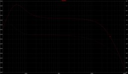
This is the amp with the 12ax7, and the harmonic content with 2,5 Vp at its input:
Not bad for a bass amp, and probably it can be improved by finding the right working point for the PI. 12ax7's plates have a dc point at 270V and swing from 195 to 345 V.
Code:
Harmonic	Frequency	 Fourier 	Normalized	 Phase  	Normalized
 Number 	  [Hz]   	Component	 Component	[degree]	Phase [deg]
    1   	1.000e+03	7.954e+01	1.000e+00	   -1.16°	    0.00°
    2   	2.000e+03	7.238e-02	9.100e-04	   72.07°	   73.24°
    3   	3.000e+03	1.305e+00	1.640e-02	  144.37°	  145.53°
    4   	4.000e+03	1.985e-02	2.495e-04	   78.70°	   79.87°
    5   	5.000e+03	3.755e-01	4.721e-03	  145.95°	  147.11°
    6   	6.000e+03	2.019e-03	2.538e-05	 -119.86°	 -118.69°
    7   	7.000e+03	4.360e-02	5.481e-04	  -20.80°	  -19.64°
    8   	8.000e+03	1.724e-03	2.168e-05	 -142.47°	 -141.31°
    9   	9.000e+03	3.944e-02	4.959e-04	  -35.60°	  -34.43°
Total Harmonic Distortion: 1.710835%(1.710965%)
Not bad for a bass amp, and probably it can be improved by finding the right working point for the PI. 12ax7's plates have a dc point at 270V and swing from 195 to 345 V.
Attachments

Fixed some more details, with 2,5 Vp on the input I've got 90 Vp on 8 Ohm, that's 600 Wrms at THD 1,5%.
OT has 2k4 Raa and 20%UL.
OT has 2k4 Raa and 20%UL.
Code:
Harmonic	Frequency	 Fourier 	Normalized	 Phase  	Normalized
 Number 	  [Hz]   	Component	 Component	[degree]	Phase [deg]
    1   	1.000e+03	9.049e+01	1.000e+00	   -1.24°	    0.00°
    2   	2.000e+03	5.961e-02	6.588e-04	   67.14°	   68.38°
    3   	3.000e+03	9.263e-01	1.024e-02	  117.58°	  118.82°
    4   	4.000e+03	3.028e-02	3.346e-04	   69.50°	   70.74°
    5   	5.000e+03	1.015e+00	1.122e-02	  155.57°	  156.81°
    6   	6.000e+03	5.673e-03	6.269e-05	  130.09°	  131.33°
    7   	7.000e+03	1.357e-01	1.500e-03	   -5.18°	   -3.94°
    8   	8.000e+03	1.060e-02	1.171e-04	  -95.44°	  -94.20°
    9   	9.000e+03	3.790e-02	4.188e-04	 -157.66°	 -156.43°
Total Harmonic Distortion: 1.528475%(1.529997%)
Attachments
you right, I multiplied the power on step the voltageI'm sorry but no. 903 Wpeak and 451,5 Wrms.
Follow the calculations above.
Roberto,
as I yet said above, your design appears to get somewhat complicated as a bass guitar amplifier.
In the beginning there were heroes like John Entwistle and Chris Squire who defined a completely new role for the bass guitar in the band context: More treble, more sustain, complex and melodic bass lines, resembling counterpoint in classical music, even replacing the lead guitar with The Who. They used tube amplifiers then.
In the 1980ies this developed into sounds and playing styles with even more treble, even more sustain. Nearly HiFi-ish amplifiers were en vogue then, and they were transistorized!
Nowadays and with new technologies you have to decide IMHO: If you want it HiFi, but with some tubey touch, I'd suggest going class AB or class D output stages and a tube in the preamp section, which also might be a small power pentode with a real output transformer, feeding an appropriate speaker simulator. Or DSP it. Relatively cheap and light-weighted. But you have to compete with amps like the Ampeg PF-500: 500 watts, as small as a folder, a mass of just 5 kg and that cheap that DIY appears to become ridiculous.
If you want it more tubey and need the power, have a look at how 300 to 400 watts behemoths like Ampeg SVT, Hiwatt DR401, Fender PS400 do it: Clear and simple, hence reliable circuitry throughout, moderate NFB.
Gongs and bells like Schade feedback, UL etc. are only necessary if you need real HiFi reproduction instead of a sound machine.
Best regards!
Last edited:
Hi Kay,
and thanks for your suggestion. I never asked how your bass amp sounds, and what was the impressions of es345 on his amp. Can I ask you?
Talking about instrument amplifiers with UL, I really like Dr. Z Amps that use UL instead of conventional NFB from speaker to PI. I also had an Advance amp with UL and (almost) no conventional NFB, and it was very good.
I've built many all tube amps for guitar and very few bass amps (with tube preamps, a mosfet source follower for the loop, and then a Class D power amp), I don't like small all tube amps for bass instrument amplification, while I do like tube preamps and class D power amps, but this time I would like to experiment something different.
From what I know, 20% UL is more focused on maximizing power rather than minimize distortion, and the shade seems an interesting way to have a shorter feedback path to reduce output impedance. I abandoned current feedback by now, following your suggestion to simplify it. There will be also only two Powerdrive systems, not six as before, and I'll follow es345 path in selecting the tubes.
I don't gig and I'm not interested into start a mass production of those amps. It will be just for me, and from here to beginning to assemble it there will be way more steps (EG finding the right mosfets for CCS and the Powerdrive). Most probably I will let a professional person do the final part of the construction, as I usually work at 500 V for B+, not 900 v, and I have to say I'm worried to do something wrong.
Basically it will be a es345 amp with:
- a better CCS on the PI
- shunt feedback
- a CCS on the Powerdrive
- 20% UL taps
- less-to-no NFB
But I've read about his impressions when used without feedback at all and he was very happy. And the situation improved when he applied some feedback to it.
Do you think this amp will be so far from his amp?
Roberto, remark that the 3rd and 5th harmonics are nearly of opposite phase, that are those that reduce the distortion of the loudspeaker. I think your precedent current feedback is more useful for a musician .The amp distortion makes part of the sound character along with the speaker's which at 50hz can be 20% at 10w. I am not a conesseur about the subject , but what is the natural sound of bass guitar is unknown .
Last edited:
Thanks, can I ask you some links where to read more about this? What is the expected result depending on the phase of the distortion, and what is the accuracy for this based on available models?Roberto, remark that the 3rd and 5th harmonics are nearly of opposite phase, that are those that reduce the distortion of the loudspeaker.
By now I've found something here: Audibility of 3rd harmonic
Thanks, I will try to do some simulations with 100 mOhm from ground to the OT secondary with 1k in series to inject some current feedback into the NFB path.I think your precedent current feedback is more useful for a musician .The amp distortion makes part of the sound character along with the speaker's which at 50hz can be 20% at 10w. I am not a conesseur about the subject , but what is the natural sound of bass guitar is unknown .
Based on this post by gingertube: EL34 Baby Huey Amplifier
So here as well we have 100 Vpp more reasonably at 50 kHz slewrate will be:
2 x pi x f x V = 2 x 3,14 x 50 kHz x 100 = 31,4 V/us
Three GU50s in parallel will have around 45 pF input capacitance.
C = i x dt / V
dV/dt = 31,4 V/us
then
45 pF = i / slewrate
so
i = 45 pF x 31,4 V/us = 1,41 mA
So it can be enough to have 470 Ohm on the CCS.
I will keep 390 Ohm and 1,7 mA.
An update with current feedback.
Code:
Harmonic	Frequency	 Fourier 	Normalized	 Phase  	Normalized
 Number 	  [Hz]   	Component	 Component	[degree]	Phase [deg]
    1   	1.000e+03	9.159e+01	1.000e+00	   -4.07°	    0.00°
    2   	2.000e+03	6.630e-02	7.239e-04	   49.05°	   53.12°
    3   	3.000e+03	1.113e+00	1.215e-02	   84.25°	   88.31°
    4   	4.000e+03	1.018e-01	1.112e-03	   75.65°	   79.71°
    5   	5.000e+03	1.977e+00	2.158e-02	  143.38°	  147.45°
    6   	6.000e+03	3.291e-02	3.593e-04	 -120.58°	 -116.51°
    7   	7.000e+03	4.210e-01	4.597e-03	  -26.03°	  -21.96°
    8   	8.000e+03	1.709e-02	1.866e-04	   54.34°	   58.41°
    9   	9.000e+03	2.194e-01	2.395e-03	  133.42°	  137.49°
Total Harmonic Distortion: 2.534354%(2.542032%)
Attachments
I was reading about Wolcott amps and their use of local shunt voltage feedback and positive current feedback here:
HiFiForum.nu - Henry Wolcott and the secrets behind his amplifier
and I've discovered I'm spinning a 60 years old weel:
US3111630A - Wide range high fidelity balanced amplifier
- Google Patents
It is interesting also the point related to resistors 29 and 30 on the bottom of the PI:

An the aspect related to the capacitor between the cathodes of the PI:
HiFiForum.nu - Henry Wolcott and the secrets behind his amplifier
and I've discovered I'm spinning a 60 years old weel:
US3111630A - Wide range high fidelity balanced amplifier
- Google Patents
There is yet another benefit to this scheme, namely the effect that it has on
clipping. Typical high gain, high feedback amps misbehave badly when overloaded.
Clipping effectively disengages the negative feedback loop because the voltage at the
output no longer bears a linear relationship to the input so progressively less feedback is
available. That in turn increases the gain of the circuit so the gain device is pushed right
up against its voltage rails for abrupt, severe, flat-topped clipping. That doesnt happen
with our design because the positive feedback loop, which engenders most of the gain in
the circuit, is progressively decoupled as well as the negative feedback loop, so the circuit
doesnt take off in the presence of overload. Because clipping will occur only in the
output stage under normal circumstances, the basic disproportion in gain between main
voltage swinger and output will still be present far into overload, though diminished and
thus the behavior of the amplifier under conditions of hard clip will actually be better
than a typical low feedback, push-pull vacuum tube amplifier.
It is interesting also the point related to resistors 29 and 30 on the bottom of the PI:
FIG. 7 shows the results of harmonic distortion as a function of circuit unbalance. This is for the embodiment of FIG. 2 for a signal frequency of 1,000 cycles. The lower curve, labelled two resistors, gives data for the circuit with resistors 2? and 30. The same data for only one resistor in place of the two, 29 and 30, is shown in the upper curve labelled one resistor. it is seen that the harmonic distortion is less than half as great for nominal values of unbalance and less than one-third as great for an unbalance of 15%. The small values of distortion, in the small fractions of one percent, are also to be noted. These measurements included residual noise also.
An the aspect related to the capacitor between the cathodes of the PI:
A self-balancing aspect is provided by separate cathode resistors 29 and in PEG. 2. These have typical values of the order of 400,000 ohms each when the voltage of battery 31 is 150 volts.
Resistors 29 and 30 actually set the current passed by each half of dual triode 5. The DC. potential of each grid of vacuum tube 5 is positive with respect to ground by virtue of the voltage divider from the full power amplifier plate voltage formed by resistors 2 and 1 and one-half of resistor 26; to consider the upper half of the amplifier as drawn in FIG. 2. Accordingly, current flows in each triode of tube 5 until the potential of each cathode is, say, 1 /2 volts more positive than the voltage on that grid. The usual desired negative grid bias with res, ect to the potential of the cathode is thus established.
A diiference in the DC. potentials between grids due to inequality of the values of resistors 2 and 4, or i and 3, will not affect the operating grid bias because the resulting potential difierences are small with respect to the 150 volt value of negative supply voltage 31. The plate current of the triode is not appreciably afiected.
The plate current I is determined by the relation:
where:
E=voltage of supply 31 (as -l v.) E =voltage on grid of tube 5 (as plus 10 v.) Rg=resistance of resistor 29 (as 400,000 ohms) It is seen that if 5,, is small with respect to E the value of I will not be appreciably affected by a change in value of E Batteries have been shown throughout PEG. 2 for sake of circuit completeness, but it will be understood that known positive and negative A.C. to DC. power supplies may be employed instead.
The above circuit aspects further meet the second and third circuit conditions that were previously set forth.
Capacitor 32 in FIG. 2 is provided to maintain both cathodes of tube 5 at the same alternating current potential by presenting a very low impedance between these elements. This occurs although the direct current potential of each cathode may be different because of the self balancing mechanism just explained. A capacitance of the order of 25 microftarads is suitable for capacitor 32. If this is of the electrolytic variety it should be of the nonpolarized type, since the polarity between the cathodes of tube 5 may be in either direction.
I'm reading some documents and it explains it in this 1938 document (page 363):Schade uses 10% without explaining why.
http://www.mcmlv.org/Archive/TubeTheory/Schade 1938 Beam Power Tubes.pdf
The high power sensitivity of the beam power tube requires the value of only 10 per cent feedback to effect a loud-speaker damping equal to that obtained with class A1-operated low-impedance triodes.
- Home
- Amplifiers
- Tubes / Valves
- 450W bass amp: a sextet of GU50s with shunt¤t feedback