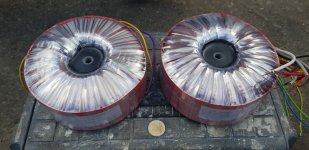
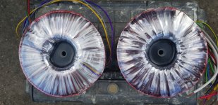
As I did in 2012. Mr. Wiesmayer proved to be a very helpful man during several phone calls, which eventually led me to order a set of transformers. Being more conservative, I got them designed along the EL 152 datasheet mentioned previously by me, hence a plate to plate load of 2k7, but a plate supply voltage of 900 V. Either the PT and the OT were wound on toroid cores good for 1000 VA. I paid about € 370 for both. Dimensions were about 170 mm dia and 75 mm height (larger than the values Badel specifies for their 1 kVA toroids, due to many windings for the PT and extensive insulation for the OT). Weight is about 6.5 kg each.I've contacted the German/Polish company to have an idea of the price, weight and the limits of the PT and OT they can supply.
Best regards!
Great information Kay,
I will most probably go in between the previous 2 kOhm Raa used by es345 and your 2k7.
Let's consider 450 € considering the price increase and transportation.
Well, from now to the order of the trafos the road is still long!
I will most probably go in between the previous 2 kOhm Raa used by es345 and your 2k7.
Let's consider 450 € considering the price increase and transportation.
Well, from now to the order of the trafos the road is still long!
I now understand much better what you are trying to achieve.
I have a question in return. Are you designing a guitar bass amp or a sub for your Hi-FI system? The reason I ask is because in a guitar bass amp 3% distortion may be just fine whereas in a HI-FI amp you may wish < .5%.
I have a question in return. Are you designing a guitar bass amp or a sub for your Hi-FI system? The reason I ask is because in a guitar bass amp 3% distortion may be just fine whereas in a HI-FI amp you may wish < .5%.
The advantage of using current transformer (not my idea, I borrowed it from industrial equipment) is that you can tune the secondary, and make it effective over the interested range of frequencies of interest, generally, the lower end, although I found it unnecessary in my prototype. Also, it isolates the DC paths, so series adder like mine make is easier to combine both loops independently, and the range of the positive feedback added. I do it in the secondary, and a too high degree of feedback makes the amplifier unstable, and I don't need to use strange pot values, as the true secondary load for the trafo is fixed low value resistor. Also, the load over the secondary gives you a way to manage the Q of the circuit, turning quickly or not the positive into negative feedback as frequency increases, a desired effect to prevent oscillations.
I suggest to search in the web for an article from J. Ross Macdonald who designed an amp with positive current feedback and give good guidelines as he did it. Also there are some interesting ideas in the Google Patents.
Good luck.
I suggest to search in the web for an article from J. Ross Macdonald who designed an amp with positive current feedback and give good guidelines as he did it. Also there are some interesting ideas in the Google Patents.
Good luck.
Ciao baudolin0, I know an instrument amp should be posted here:
https://www.diyaudio.com/forums/instruments-and-amps/
but I would like to design it with both functions you mentioned, and due to the fact that it's strongly based on BH ideas, I thought this would be better than the other section of the forum, because more people is used to work with these aspects, simplifying its developement and the condivision of experiences and ideas.
Some more suggestion: I've ordered the PT with a shield winding on top of the primary (that needs to be connected to PE) and a belly band around all the windings to minimize stray.
Btw, the Polish winding shop first has forgotten the shield winding, but Mr. Wiesmayer arranged the PT to be fixed quickly.
Best regards!
Btw, the Polish winding shop first has forgotten the shield winding, but Mr. Wiesmayer arranged the PT to be fixed quickly.
Best regards!
I suggest to search in the web for an article from J. Ross Macdonald who designed an amp with positive current feedback and give good guidelines as he did it. Also there are some interesting ideas in the Google Patents.
Good luck.
Thank you Osvaldo,
this evening I will read these files:
https://jrossmacdonald.com/jrm/wp-content/uploads/025ActiveErrorFeedback.pdf
https://jrossmacdonald.com/jrm/wp-content/uploads/026MultiloopAmplifier.pdf
and will do further research on patents as per your suggestion.
One more time, thank you Kay! I was not aware of this trick!Some more suggestion: I've ordered the PT with a shield winding on top of the primary (that needs to be connected to PE) and a belly band around all the windings to minimize stray.
As a technical sales person I'm always happy to see that good professional people are the ones everyone remembers even after years. 🙂Btw, the Polish winding shop first has forgotten the shield winding, but Mr. Wiesmayer arranged the PT to be fixed quickly.
Best regards!
OK. What part of Italy are you from? My grandfather's were from Crottone, in the south.
Take care with the phase rotations in forward loop. Mainly at both audio ends. I haven't this trouble because I used fully DC couplings, and cathode follewers between stage to reduce the importance of the high en rolloff's.
If you are interested, send me a PM and i shall send you a complete schematic of my project, unfinished by now, but still working successfully.
Bueno Osvaldo, mi abuela naciò en Montevideo y viviò en Buenos Aires tambien.
I live in the northern part of Italy.
I'm planning to use only resistors in both voltage and current feedback paths.
I'm sending you a PM, I'm very interested into!
I live in the northern part of Italy.
I'm planning to use only resistors in both voltage and current feedback paths.
I'm sending you a PM, I'm very interested into!
Well, especially in a musical instrument amplifier a protective shield between the primary and secondary windings IMHO is mandatory for safety reasons.
Re positive current feedback: I assume your goal with it is to get the damping factor as high as possible, which is a good idea in a bass guitar amp (I'm not tinkering with it, though). What you were showing to us in your first schematic allows to dial between different levels of positive as well as negative current feedback. Did you intend that?
For PFB only I'd omit the resistor between ground and the speaker gnd terminal and arrange the OT phasing to fit. And I'd also add some amount of voltage NFB, using a divider, as usual, whose lower resistor returns to the trimpot's wiper.
Best regards!
Ciao baudolin0, I know an instrument amp should be posted here:
https://www.diyaudio.com/forums/instruments-and-amps/
but I would like to design it with both functions you mentioned, and due to the fact that it's strongly based on BH ideas, I thought this would be better than the other section of the forum, because more people is used to work with these aspects, simplifying its developement and the condivision of experiences and ideas.
Posting it here with probably get you more advise than the instrument forum. I more interested because your target THD will affect the complexity of the design.
I think just taking a step back and working out what your design targets may help you to decide what's needed for your design and what's not - at the moment it feels like everything is being thrown in the melting pot.
For example do you need CCS on the drive mosfets or will a simple resistor down to a negative rail be just fine and make little difference to the THD and saving you a bag of components.
Last edited:
Thank you for your intervention,
Power Drive | Tubelab
Cookbook | Tubelab
It has also been discussed deeply on this forum the importance of a low impedance drive for the grids.
It would be crazy to buy 450 euros of trafos and then save 3 euros on a CCS.
I respect the way you would act, but I don't see why I should step back. This thread has 74 post of skilled persons that are apporting very useful information on what I want to implement, I'm learning alot from very generous people and the interest on the interventions of these people is confirmed by 2300 visualisations of this thread up to nowI think just taking a step back
I suggest you to read again the thread, you'll have a clearer view of the whole thing. Or maybe not.at the moment it feels like everything is being thrown in the melting pot.
I suggest you to read these links:For example do you need CCS on the drive mosfets or will a simple resistor down to a negative rail be just fine and make little difference to the THD and saving you a bag of components.
Power Drive | Tubelab
Cookbook | Tubelab
It has also been discussed deeply on this forum the importance of a low impedance drive for the grids.
It would be crazy to buy 450 euros of trafos and then save 3 euros on a CCS.
They are huge as expected. Apparently the contact I have for the SMPS I bought, can go up to 240 Vdc and 3 kW, no more than that.These are my Badel toroids, made in Poland.
This is another article about the combination of positive current and negative voltage feedback:
Special Purpose Oscillators and Amplifiers - United States. Army - Google Libri
Special Purpose Oscillators and Amplifiers - United States. Army - Google Libri
To avois any possibility to be in contact with 900 Vdc even if the OT fails. Thanks!Well, especially in a musical instrument amplifier a protective shield between the primary and secondary windings IMHO is mandatory for safety reasons.
Yes, it is a variable damping control that would be used to find the sweet spot and then fix it, with the purpose you said.Re positive current feedback: I assume your goal with it is to get the damping factor as high as possible, which is a good idea in a bass guitar amp (I'm not tinkering with it, though). What you were showing to us in your first schematic allows to dial between different levels of positive as well as negative current feedback. Did you intend that?
For PFB only I'd omit the resistor between ground and the speaker gnd terminal and arrange the OT phasing to fit. And I'd also add some amount of voltage NFB, using a divider, as usual, whose lower resistor returns to the trimpot's wiper.
Best regards!
Clear, thanks. This evening I had other things to do and I haven't sketched the new schematic, I will in the following days.
It has also been discussed deeply on this forum the importance of a low impedance drive for the grids.
I am not suggesting removing the mosfet's that is a necessary thing just the 6xCCS that go with it. I like your idea of being able to adjust the bias on each valve individually to the correct value. You could even replace them with emitter followers although there will then be some base current taken from the first stage. They would have a more constant Vbe drop without the CCS.
Just be aware that if you go for a pentode splitter in the first stage the screens may take different currents if the valves are not matched. This will effect the DC and AC balance - and you may need a balance pot.

Last edited:
baudouin0, two remarks to your schematics:
1st: I suspect V4 as a negative (-70 Vdc) voltage source is drawn upside down.
2nd: Assuming you're feeding the LTP tail with -70 Vdc, are you sure that a BC846 will stand it? What's the expected cathode voltage of both pentodes?
Best regards!
1st: I suspect V4 as a negative (-70 Vdc) voltage source is drawn upside down.
2nd: Assuming you're feeding the LTP tail with -70 Vdc, are you sure that a BC846 will stand it? What's the expected cathode voltage of both pentodes?
Best regards!
- Home
- Amplifiers
- Tubes / Valves
- 450W bass amp: a sextet of GU50s with shunt¤t feedback