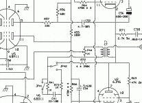
Yes, Roberto, thanks, these are what I've meant. They're part of an (incomplete) TELEFUNKEN research report on the LS 50 tube from 1941 (right out of the Führerbunker, I assume 🙄). IIRC, even operation at positive suppressor voltages had been reported there.
Best regards!
Best regards!
Sorry, no, I was referring to a TELEFUNKEN R&D report on the LS 50 tube, not just this datasheet that easily can be found in the WWW.
Maybe it was es345 who gave the document to me. Due to many changes in my IT gear since I don't have it anymore, though 🙄-
Best regards!
Maybe it was es345 who gave the document to me. Due to many changes in my IT gear since I don't have it anymore, though 🙄-
Best regards!
The load and dissipation calculation is very difficult task , particularly in class AB₂ where the load most of the time is not shared . You find a graphical means of calculation in Radio Engineering Handbook of 1940's downloadable in PDF from Americanradiohistory website. I am unable to access these days.
I lack of contacts in the Nachrichtendienste des Bundes, so I guess I'll wait for Hans-Georg to come back, or the file to appear under your eyes by serendipity.
Some interesting curves taken from wavebourn site depending on GU50 g3's voltage:
www.wavebourn.com • View topic - GU-50
g3 at 0 V:
g3 at +10 V:
g3 at +30 V:
www.wavebourn.com • View topic - GU-50
g3 at 0 V:
An externally hosted image should be here but it was not working when we last tested it.
An externally hosted image should be here but it was not working when we last tested it.
g3 at +10 V:
An externally hosted image should be here but it was not working when we last tested it.
An externally hosted image should be here but it was not working when we last tested it.
g3 at +30 V:
An externally hosted image should be here but it was not working when we last tested it.
An externally hosted image should be here but it was not working when we last tested it.
So, as smoking-amp was saying here ( a better pentode for less! ):
First, you have to find the optimum g3 voltage that minimizes g2 current at the operating point chosen. Typically +12V to +32V works on g3. (too much + g3 and the current starts going to g3 instead, NG) This is low current at g3, so a resistive divider can be used from B+ to derive this, or a zener setup.
You will find that g2 current has dropped considerably from the datasheet figure (given at g3 = 0). And this means that more current is arriving at the plate than before. (the + g3 bias prevents electron returns back to g2).
Basically there's no more need to reach AB2 as the curves are squared, and also less swing is needed from the phase inverter to get the same output power.
Has anyone ever tried this other trick?
DECWARE Christmas Comes Early aka Hazen Grid Mod / Audio Paper
DECWARE - The Hazen Mod
but measurements doesn't show anything special...
Has anyone ever tried this other trick?
DECWARE Christmas Comes Early aka Hazen Grid Mod / Audio Paper
DECWARE - The Hazen Mod
a piece of wire connecting the suppressor grid to the cathode sounds familiar, but replace the wire with a non-polarized film cap
but measurements doesn't show anything special...
I am studying an amplifier with positive current feedback via a current transformer with very good results. Bass notes are clearly reproduced without distortion still without any baffle in the speakers. It is surprising.
Attachments
Last edited:
Roberto,
assuming you bias each GU-50 for 30 mA plate current and Ub will be stable at 870 Vdc, the plate power dissipation will reach a maximum of nearly 60 watts per tube (at about 70% drive).
I'm aware I'm over the 40 W dissipation curve, but being off almost 50% of the time, using force ventilation and being bass a non constant source of sound, shouldn't it be acceptable?
Pardon me for referring to some previous postings: The dissipation of 60 watts is a mean one, it includes the fact that the tube is off almost 50 % of the cycle.
Best regards!
I'm wondering what a capacitor could do in this place 😕?
Best regards!
diyaudiopedia has an answer for everything!
Anyone try the "Hazen mod" to G3 supressor grid
I am studying an amplifier with positive current feedback via a current transformer with very good results. Bass notes are clearly reproduced without distortion still without any baffle in the speakers. It is surprising.
Thank you for your feedback Osvaldo!
I will try with simple resistors at the beginning, but I need to redraw the schematic to better explain how I want to do it, and ask if anyone has ever done it that way, using two paths from the secondary of the OT to a common resistor of each side of the push-pull.
The idea is to shorten the path of the two feedbacks (shunt and current), following Crowhurst' suggestions on feedback.
Pardon me for referring to some previous postings: The dissipation of 60 watts is a mean one, it includes the fact that the tube is off almost 50 % of the cycle.
Best regards!
Thanks Kay,
at this link: Bassendstufe BRV 250
Hans-Georg says his amp is working:
Ub: 952V
Ug2: 250V
Ug1: -43.4V (group 1) / -42.7V (group 2)
Ik: 28 mA per tube
Raa is 2 KOhm
The full schematic is here: Bass Power Amp with GU50 - Page 2
So the value indicated on the datasheet of max 50 W for max 1 minute seems that can be exceeded for an amp like a bass amp that is not a constant source of sound. What do you think?
Has anyone ever tried this other trick?
DECWARE Christmas Comes Early aka Hazen Grid Mod / Audio Paper
DECWARE - The Hazen Mod
I'm wondering what a capacitor could do in this place 😕?
diyaudiopedia has an answer for everything!
Anyone try the "Hazen mod" to G3 supressor grid
Oomph! The thread you've quoted contains much blah blah, but substantiated statements as well. One one hand it is clear and understandable what a small positive voltage at g3 does. In my understanding the behaviour of a lacking DC path to the cathode makes any grid's behaviour unpredictable, though. For certain reason any tube manufacturer calls such a path mandatory in their tube data books. As I see it, electrons that randomly hit an isolated grid will charge it negatively. Remember the grid leak bias: If a highish resistor is connected between grid and cathode, the negative charge results in some smallish DC through that resistor, biasing the grid itself. In the suggested cap modification this cap will be randomly charged, too, which leads to some negative potential at g3. This potential depends on the number of electrons (who knows exactly how many?) that hit g3 and the quality of the isolation of all involved components (envelope glass, tube holder, capacitor, leads…), hence is rather unpredictable.
In my opinion this Hazen mod was propagated just to be different, and I feel very confirmed just by the words they used for that propagation.
Roberto, if you want to do anything substantial with your GU50 g3's, set them at a smallish (max. 15 V) positive potential.
Best regards!
This is Hans-Georgs aka es345's design, isn't it?
As said before, he's an EE, hence well aware what he's doing.
Best regards!
As said before, he's an EE, hence well aware what he's doing.
Best regards!
Danke Kay,
I've collected some hints from wavebourn here:
Baby Huey enters into puberty: 6550 KT88 possibly GU50?
but as instrument amplifiers usually do, I will try to work with a lower Raa.
I've contacted the German/Polish company to have an idea of the price, weight and the limits of the PT and OT they can supply.
The idea is to stay around the value stated in the title, and possibly keep the hextet of GU50s, while two EF86s with CCS for the PI, with mosfet drivers loaded with CCS, seem the most reasonable choice to reduce the number of involved stages. Preamp signal will need very small amplification, and I could keep the EQ external using the spare Presonus EQ3B I have.
This evening I will post the amended schematic.
PS
it came to my mind that I bought, few years ago, a SMPS power supply, around 2 kW, working at around 200 V. I have to find the contact and ask if they are available for this kind of voltages (that are very differen, I know).
Ciao baudoin0,Now the penny has dropped.
can I ask you why you posted a schematic that you have found here: Bass Power Amp with GU50 - Page 2
that is part of the sources I've cited in my first post of the thread (third from the bottom) as starting points for this new project?
This is Hans-Georgs aka es345's design, isn't it?
As said before, he's an EE, hence well aware what he's doing.
It is exactly, that's why I included in the first post as a source from where start designing the new amp including the improvements developed for the Baby Huey and Crowhurst's articles.
The differences from that design are:
- the inclusion of an improved CCS and different tubes for the PI;
- the inclusion of a CCS for the mosfet drivers;
- the inclusion of the shunt feedback;
- the inclusion of the current feedback;
- the exclusion of the soft clipper before the driver (the resistor + zener +diode between PI's outputs and ground);
- the exclusion (if possible) of the global NFB as shown in that amp;
- a different power amp;
- the possibility to supply B+ through SMPS while using a small toroidal for other small power voltages.
It's quite a different penny.
- Home
- Amplifiers
- Tubes / Valves
- 450W bass amp: a sextet of GU50s with shunt¤t feedback


