xrk971
Given the DC protection for headphones ... What is the dangerous value?
Opinions are divided ...
THX.
Given the DC protection for headphones ... What is the dangerous value?
Opinions are divided ...
THX.
Hi, regarding the amp in the original/first post, does it provide enough gain? Is it possible to connect it directly (without pre-amp) to the DAC output (e.g. https://www.amazon.com/gp/product/B07KN6P9QB) and have enough power? Thanks!
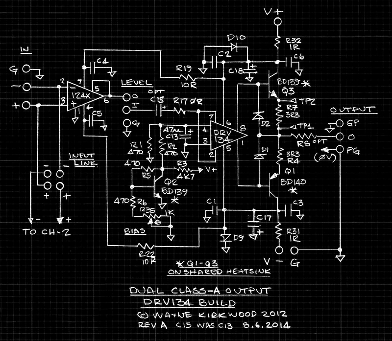
I am told by Mediatechnology that this is an updated schematic if one wants to use the DRV134 (I love his old school “blue print” style hand drawn schematics, btw):
Technical discussions can be found here:
Dual Class-A Line and Headphone Output Board Documents - Pro Audio Design Forum
Technical discussions can be found here:
Dual Class-A Line and Headphone Output Board Documents - Pro Audio Design Forum
Last edited:
xrk971
Given the DC protection for headphones ... What is the dangerous value?
Opinions are divided ...
THX.
On headphone SSR DC protections that I have built in the past, I use 500mV lasting longer than about 100mS as the trigger point. I think most headphones can handle 1V DC just fine for a few seconds without damage so 500mV for sub 10Hz wave seemed to be good. It’s adjustable to taste and application of course.
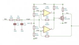
Here is the comparator circuit we used to detect DC offset error:
Attachments
Check out the OPA1622 then, zero transistor amplifier!
+1
For those who would rather not solder the itty-bitty SMD package the OPA1622 comes in should consider using the $25 EVM from TI. Add a buffer and volume control for even better performance.
Tom
I used the 5 transistor version PNP input NPN vas PNP current source and IRF530,9530 outputs
in a car amp back in 1990 - 2016. this topology gives excellent specs.
not sure if performance is better reversing the BJT's
NPN input PNP vas NPN current source.
in a car amp back in 1990 - 2016. this topology gives excellent specs.
not sure if performance is better reversing the BJT's
NPN input PNP vas NPN current source.
Last edited:
Hi, regarding the amp in the original/first post, does it provide enough gain? Is it possible to connect it directly (without pre-amp) to the DAC output (e.g. https://www.amazon.com/gp/product/B07KN6P9QB) and have enough power? Thanks!
Plenty of gain for me to use a SA9227+PCM5102A DAC or even straight from mobile phone.
The DAC is usually set about 9% volume for comfortable listening levels with 38 ohm headphones, so if anything, the gain could probably be reduced.
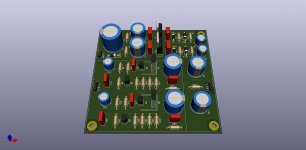
The final version that I am using is this one and it sounds very good to me:
Attachments
avtech23, thank you for the updated schematic!
If I'll use 22K pot for volume control should the parameters for the input filter change in this case?
If I'll use 22K pot for volume control should the parameters for the input filter change in this case?
Thank guys!
I had no idea this circuit would be liked by people.
But when I made it, it tested well in my spice model circuit.
It is good, otherwise I dont post circuits.
LM317 is a perfect choise for the supply.
I had no idea this circuit would be liked by people.
But when I made it, it tested well in my spice model circuit.
It is good, otherwise I dont post circuits.
LM317 is a perfect choise for the supply.
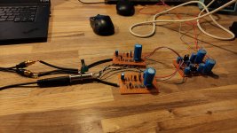
Thanks for the circuit Lineup. It was good to play around with it and make a board with your circuit.
I've been using mine for a while now and feel that it outperforms my Hakuin and O2 amps when used with the ATH-M50X. Plenty of power to drive pretty much anything.
The LM317 has proven to be a good match and doesn't seem to induce noise into the amp. I swapped in an LDO, but the measurements and listening did not change.
Good Stuff
Hi,
want to build it myself, but i cant seem to find BC550C and BC560C transistors. What will be a good substitute for them ?
want to build it myself, but i cant seem to find BC550C and BC560C transistors. What will be a good substitute for them ?
I used BC550CTA and BC557CTA from Mouser.
Try find alternates that are available locally by searching All Transistors. Datasheet. Cross Reference Search. Transistor Database. with BC550 and BC560.
Try find alternates that are available locally by searching All Transistors. Datasheet. Cross Reference Search. Transistor Database. with BC550 and BC560.
Thanks for reply.
I found BC547 and BC557. Are they good alternative ?
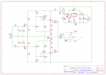
also have drawn schematic according to the schematic posted by avtech23
I am a bit confused about the signal ground and power ground. Is there suppose to be star ground ?
is the schematic correct ? as i have not started to make the pcb layout yet.
I found BC547 and BC557. Are they good alternative ?
also have drawn schematic according to the schematic posted by avtech23
I am a bit confused about the signal ground and power ground. Is there suppose to be star ground ?
is the schematic correct ? as i have not started to make the pcb layout yet.
Attachments
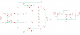
The schematic in post #67 is the one that I have been using successfully.
I split the audio GND and the power supply GND and physically connected them at the DC barrel connector. I think it doesn't really make much difference to something that only draws 200mA (I don't expect there would be huge charging pulses to deal with like a power amp, but I may be wrong). I achieved a very low noise amp in the end, so it didn't hurt anything to do it this way.
I tamed oscillations with a minimum 220pF at your C9/C10. I think I went up to around 330pF.
The LM317 is set up for 12v output, but this requires the very minimum of 4v difference between in and out (i.e. 16V in). I powered it with an 18V PSU to ensure a decent margin, but this would work with a 19v laptop charger quite nicely too.
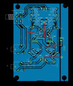
So came up with this PCB layout.
Its single layer with jumpers on top layer / red lines.
Any suggestions improvements would be highly appreciated as I will be using toner transfer method to make PCB.
initially had the power supply on the same pcb but i decided it should be on separate pcb so i can re-use.
the PCB size is 100mm x 70mm.
Also will 1/4 watt resistors do ? or do i need 1watt ones.
Attachments
When you avtech23 say the circuit outperform other amplifiers, I am not very surprised.
The benefit of this circuit is mainly the short distance from input to output.
For example opamps have a very long way from in to out.
There are many components inside the opamp that the signal must pass.
The benefit of this circuit is mainly the short distance from input to output.
For example opamps have a very long way from in to out.
There are many components inside the opamp that the signal must pass.
- Home
- Amplifiers
- Headphone Systems
- 3 Transistor HP Amplifier with low dist