Thanks for the tips, X.
I'd been looking through various texts to learn how to set up an input properly, but most seem to skip that stage and go straight to the VAS. I can't even remember where I saw the 100n, but I must have copied it from other designs I'd seen.
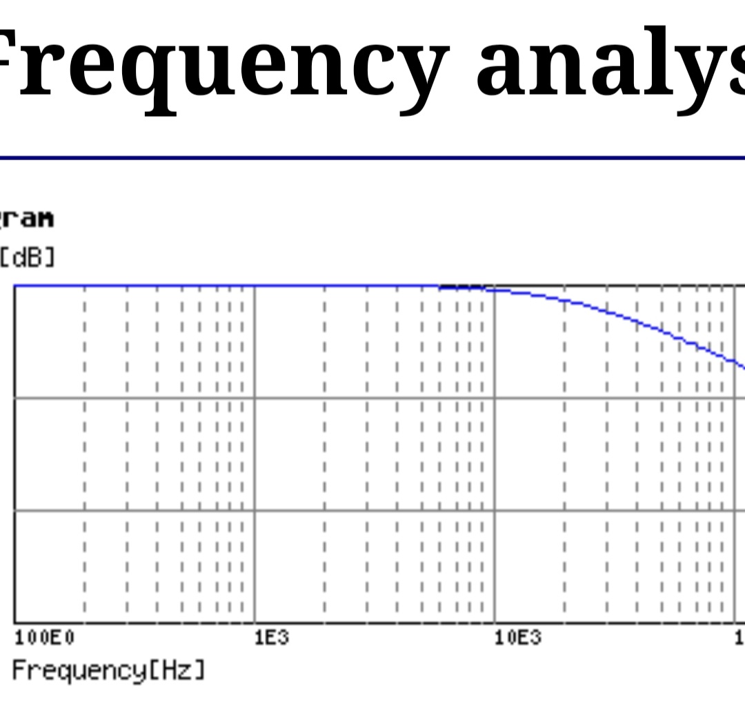
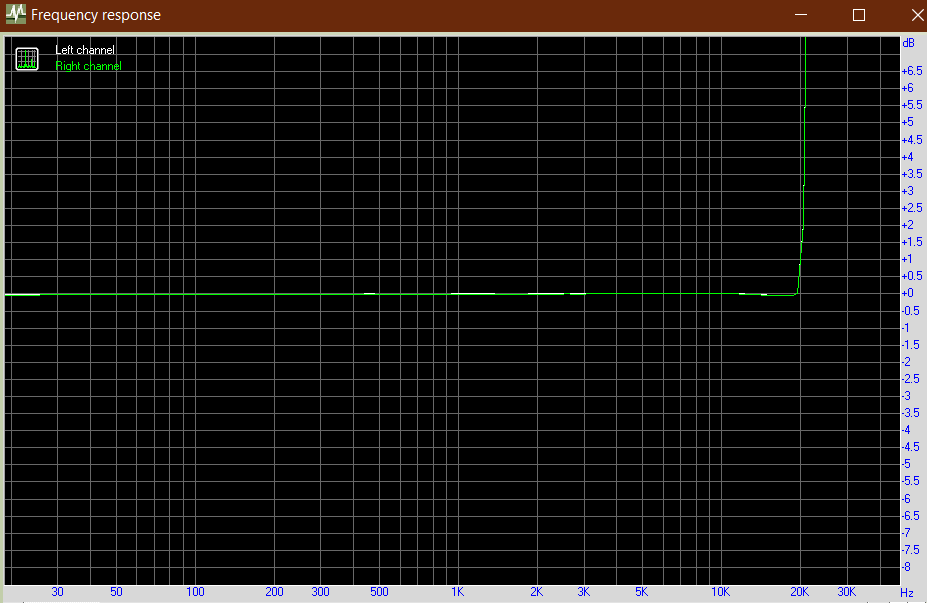
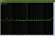
It all makes sense now that I stop and think about it and the calculated frequency response does tally up with what I was using - 75ohm output impedance of the DAC into 100nF gives this:
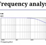
Vs. real life:

It should be simple enough to retrofit a board with the proper filter values and I'll give it another test and see how it compares.
Fun stuff and a learning process at the same time!
I'd been looking through various texts to learn how to set up an input properly, but most seem to skip that stage and go straight to the VAS. I can't even remember where I saw the 100n, but I must have copied it from other designs I'd seen.
It all makes sense now that I stop and think about it and the calculated frequency response does tally up with what I was using - 75ohm output impedance of the DAC into 100nF gives this:
Vs. real life:
It should be simple enough to retrofit a board with the proper filter values and I'll give it another test and see how it compares.
Fun stuff and a learning process at the same time!
Attachments
Last edited:
Freq = 1/(2pi x R x C) and for 75ohm and 100nF, I get -3dB at 21kHz. Matches your measured graph.
Hello,
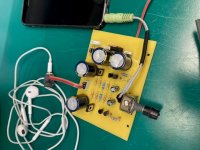
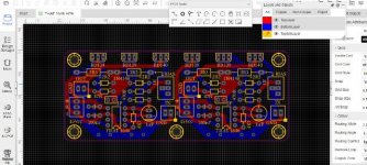
I also finished the stereo amplifier.
I used BC546, BC556 and BD139.
It sounds great.
I present you some pictures.
I will have to mention radiators on the BD139 transistors and the 7812 voltage regulator that I used.
I also finished the stereo amplifier.
I used BC546, BC556 and BD139.
It sounds great.
I present you some pictures.
I will have to mention radiators on the BD139 transistors and the 7812 voltage regulator that I used.
Attachments
If you say that it sounds very good with a phone as a signal source and you do the audition with those headphones, it's clear. Anything can sound good.
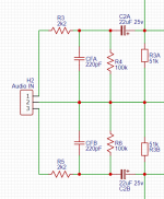
I added the filter to the second board I built as follows:
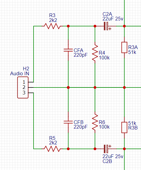
This has flattened out the frequency response:
And THD now 0.00362%:
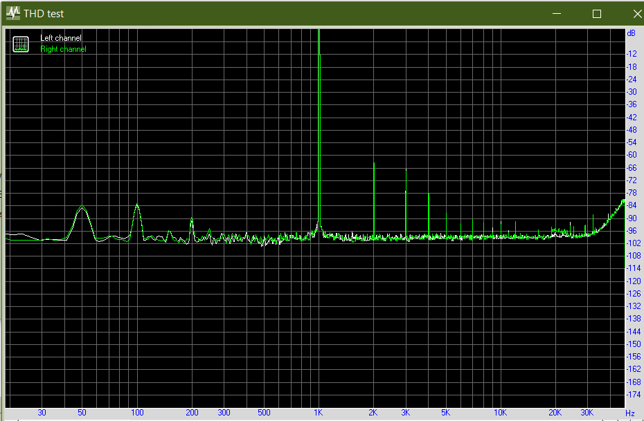
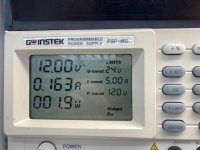
As a reminder, I measured my O2 head amp using the same set up. The O2 is specified at 0.0016%, I measured 0.00490%. The T3 under the same conditions is 0.00362%, so it is in the same ball park.
These are the figures:
Noise: -98.4dBA
Dynamic Range: -99dBA
THD: 0.00362%
IMD+n: 0.00456%
Crosstalk: -70dB
The only issue I have is lots of buzzing when nothing is connected to the input, and the buzzing goes away when I touch the metal part of the case (which is connected to the negative). When there is an input connected (even an ungrounded source such as a mobile phone), the amp is dead silent.
This has flattened out the frequency response:
And THD now 0.00362%:
As a reminder, I measured my O2 head amp using the same set up. The O2 is specified at 0.0016%, I measured 0.00490%. The T3 under the same conditions is 0.00362%, so it is in the same ball park.
These are the figures:
Noise: -98.4dBA
Dynamic Range: -99dBA
THD: 0.00362%
IMD+n: 0.00456%
Crosstalk: -70dB
The only issue I have is lots of buzzing when nothing is connected to the input, and the buzzing goes away when I touch the metal part of the case (which is connected to the negative). When there is an input connected (even an ungrounded source such as a mobile phone), the amp is dead silent.
Attachments
Add a 10ohm resistor and two anti parallel 1n400x diodes plus 22nF film cap (all in parallel) for a ground loop breaker (GLB) between your analog ground and wall plug “earth” ground). Tie the chassis to the earth ground on the dirty side of the GLB.
That might make that hum go away. But we never listen to an amp with no signal connected anyway.
That might make that hum go away. But we never listen to an amp with no signal connected anyway.
I've used that with good effect before, but the power supply for this one is the double insulated SMPS type that has no earth connection.
I do have a 'signal ground's which is connected via star to the power ground, so I could try isolate it there.
But as you say, we dont listen without it connected to something,so it's a minor issue in the scheme of things.and probably just best left alone.
I do have a 'signal ground's which is connected via star to the power ground, so I could try isolate it there.
But as you say, we dont listen without it connected to something,so it's a minor issue in the scheme of things.and probably just best left alone.
Hi avtech23, the O2 to which you compare this amp has a a volume control. How can I add it to this amp? Thanks!
marin cornel, thank you!
Is it required to have 100K pot? I'm just wondering if it would be possible to use digital pot like this: Overview | Adafruit DS1841 I2C Logarithmic Resistor | Adafruit Learning System
which is 22K max? I'm planning to build the integrated amp which will also include the headphone amp (still not decided which one to use). There will be Raspberry Pi to control the whole system. It could also control volume over I2C using that digital pot.
Thanks!
I put that value of 100k just so it turned out ...
In reality I use a 20K potentiometer, that's how I had it at hand.
I think it will work very well with what you want to use.
In reality I use a 20K potentiometer, that's how I had it at hand.
I think it will work very well with what you want to use.
marin cornel, thank your for the clarification!
I've just posted the overall design for that amp here: Infineon MA12070 Class D
I've used O2 as the example of the headphone amp but more likely I'll use the amp described in this thread.
Best regards
I've just posted the overall design for that amp here: Infineon MA12070 Class D
I've used O2 as the example of the headphone amp but more likely I'll use the amp described in this thread.
Best regards

Does this qualify as a 3 transistor low distortion headphone amp?
I have built it and it measures well and sounds great. Very easy to build.
Simple Class A Headphone Amp Using THAT1646
You killed us with that amplifier. 🙂
I will make some pcb according to Prasi's drawing, if I have time ...
I will make some pcb according to Prasi's drawing, if I have time ...
Attachments
Last edited:
There’s Gerbers for Prasi version here:
http://www.diyaudio.com/forums/atta...73d1509207246-esp-hpa-gerbers-ha-r1-2-pcb-zip
http://www.diyaudio.com/forums/atta...73d1509207246-esp-hpa-gerbers-ha-r1-2-pcb-zip
Keep in mind that it’s 0dB gain so you might want to add a voltage gain stage ahead of it. Or use a preamp capable of +/-15v output.
Does this qualify as a 3 transistor low distortion headphone amp?
It does only have 3 transistors... but I kinda feel that using a line driver is cheating 😉
(Going to look at ordering some THAT1646s now!)
Keep in mind that it’s 0dB gain so you might want to add a voltage gain stage ahead of it. Or use a preamp capable of +/-15v output.
 Yes, sir!
It does only have 3 transistors... but I kinda feel that using a line driver is cheating 😉
(Going to look at ordering some THAT1646s now!)
Nothing wrong with using a line driver - not cheating in my book 🙂
THAT1646 might be getting scarce. DRV134 from TI works too. Modify circuit per schematic note on bottom left.
If you want to go crazy, use DRV134 and some big fatty TO247 BJTs. Like TTC5200 and TTA1493. Use 0.22ohm 3W emitter resistors. Use +/-19v laptop bricks in series and set bias for 1.2A. Use 18v Zener diodes to ground on DRV134 rails.
Makes for a 10w into 8ohm Class A amp. It can drive ANY headphone to ear bleed levels 🙂 Mediatechnology (Wayne Kirkwood) has some nice simple but far out designs!


This was Kirkwood’s build:

I would seriously think about using SSR DC protection circuits before connecting a nice set of headphones to it though.
Last edited:
- Home
- Amplifiers
- Headphone Systems
- 3 Transistor HP Amplifier with low dist