I have worked a little bit more with this circuit.
Changes:
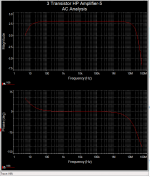
Added one 22pF compensation cap.
The bandwidth is impressive - more than 20 MHz!
See first image.
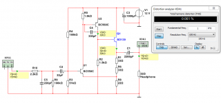
Change R5 to be 1.8k.
Change R2 to be 1.5K.
This gives a bit lower distortion.
See second image for the revised circuit.
Changes:
Added one 22pF compensation cap.
The bandwidth is impressive - more than 20 MHz!
See first image.
Change R5 to be 1.8k.
Change R2 to be 1.5K.
This gives a bit lower distortion.
See second image for the revised circuit.
Attachments

I recommend to look at Post #67.
At the input you should use some filtering. Lowpass.
One resistor and one capacitor. 2k2 and 220p.
This is very important because the amplifier is so fast.
At the input you should use some filtering. Lowpass.
One resistor and one capacitor. 2k2 and 220p.
This is very important because the amplifier is so fast.
I might try one of the units with the altered R5 and R2 values to see what the difference in performance is.
Using an oscilloscope I found that I could not get lower than 220pF on C4 without the amp taking off.
Using an oscilloscope I found that I could not get lower than 220pF on C4 without the amp taking off.
No. No problem.
In fact it is even better with 80 Ohms.
The gain is enough for that and also the current is no problem at all.
On the other hand 16 Ohms headphones instead of 32 ohms,
that could eventually be an issue.
But I think even 16 ohms headphones will be alright.
In fact it is even better with 80 Ohms.
The gain is enough for that and also the current is no problem at all.
On the other hand 16 Ohms headphones instead of 32 ohms,
that could eventually be an issue.
But I think even 16 ohms headphones will be alright.
Thanks for this info.I might try one of the units with the altered R5 and R2 values to see what the difference in performance is.
Using an oscilloscope I found that I could not get lower than 220pF on C4 without the amp taking off.
The performance is very tiny bit better with R5 and R2 change.
You can hardly notice it. Maybe measure it.
Thank you for having tested the value of C4.
I will start using 220pF in my spice simulation.
Also should we recommend using 270 or 330 pF to be on the safe side.
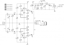
Here below is the schematic as we recommend it today.
Notice I changed the output capacitor to 2200uF.
But there is not much wrong using 1000uF.
Attachments
Last edited:
Hi, I'd like to use the following pot for the volume control over I2C:
Adafruit DS1841 I2C Digital 10K Potentiometer Breakout [STEMMA QT / Qwiic] : ID 4570 : $5.95 : Adafruit Industries, Unique & fun DIY electronics and kits
Should I change any input filter parameters in this case?
Thanks!
Adafruit DS1841 I2C Digital 10K Potentiometer Breakout [STEMMA QT / Qwiic] : ID 4570 : $5.95 : Adafruit Industries, Unique & fun DIY electronics and kits
Should I change any input filter parameters in this case?
Thanks!
You'll need two of them. At a glance it does not appear to be designed for audio use. The impedance is suitable. I'm still checking the data PDF for the DS1841's tolerance of bi-polar signals. Will get back to here soon.
Cheers
Cheers
Last edited:
I'm not finding any of the usual signs that this part is intended for audio use ..
- no distortion graphs
- no noise specs
- no mention of tolerance of signal excursions below ground
- no mention of audio under Applications (on the first page)
Can't quote a p/n offhand, but there certainly are plenty of this type of part around that come with the necessary documentation, and many even provide their own negative supply (single supply, bi-polar signals permitted).
Additionally, this part has a lot of silicon area devoted to functions that you probably don't need -- supply voltage monitoring, temperature compensation w/onboard lookup table for accuracy, and an ADC to serve them.
Maxim's DS1841 s really a remarkable part for $1,95 (Mouser) -- especially if you need the extra stuff. Bet some instrumentation applications could really make hay with it. I would not recommend it for this use.
Cheers
edit: Forgot -- the input filters are fine; an electronic volume pot probably belongs after the filter.
Last edited:
When using any potentiometer we should lower the capacitor from 220 to at least 100pF.Hi, I'd like to use the following pot for the volume control over I2C:
Adafruit DS1841 I2C Digital 10K Potentiometer Breakout [STEMMA QT / Qwiic] : ID 4570 : $5.95 : Adafruit Industries, Unique & fun DIY electronics and kits
Should I change any input filter parameters in this case?
Thanks!
Because input filter will depend on the volume control.
Another option is to put the input filter BEFORE the potentiometer.
In that case we do not change any value of the filter.
Hi daemon123,
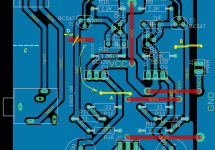
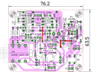
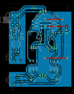
Have been looking over your PCB -- pretty nice -- many good attributes.
The ground trace has the load return currents passing the full perimeter of the board, including past the input connectors. Better to make cuts at 'C' and 'D', then provide the ground for the output from along the lower edge. Also, the ground along the right edge looks separated unnecessarily (or at least I couldn't think of a reason for it).
But you could start by moving the indicated jumper 'A'; that improves the current path for the Collector-load resistor (1k5 / 1k8, I can't remember) of the second stage.
Then, more space will be needed for the larger output Emitter resistors -- but somebody already mentioned that.
That's my two bits. But there're plenty of sharper minds than mine on this site. You are more than welcome to entertain other opinions -- won't hurt my feelings even a little. 😉
Cheers
edit: Pretty sure the input filter DOES need to be before the solid-state pot. Wanna catch that EMI before it gets to anything that could demodulate it.
Attachments
Last edited:
That's right - pot after the input filter, or as lineup said, reduce the filter capacitance so that you allow for the additional resistance of the pot to affect the RC values of the filter. But this does mean your input filter cut off value will depend on the position of the pot, which isn't ideal.
I agree with working on your grounding. For example you have areas that have become 'islands' with the ground pour. And areas that if you seperate the traces a little more, will fill in and not be void.
You also have the input and output quite close together. I like to move these apart to prevent any influence of the output on the sensitive input area.
As already mentioned, you need larger package sizes for the output resistors, but also think about heat generation. I elevated these from the board. Depending on your preference, you might want to attach heatsinks to the BD139. I have some units with and some without. They are within their SOAR rating without heatsinking, but I like to keep things cool.
I also used 2 or 3 watt output resistors to have a greater safety margin. I found some vishay metal film that came in a small package. PR02 or PR03 series from memory. Again, personal preference (40°c+ is common here) but minimum is 1w.
BC547 and BC557 are almost the same.Thanks for reply.
I found BC547 and BC557. Are they good alternative ?
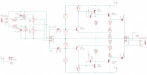
also have drawn schematic according to the schematic posted by avtech23
I am a bit confused about the signal ground and power ground. Is there suppose to be star ground ?
is the schematic correct ? as i have not started to make the pcb layout yet.
So they should work.
Especially the C flavour. BC547C
...I would not recommend it for this use.
I believe logarithmic scale assumes that it can be used in audio projects. Anyway, I bought two of them already 🙂 I'll try to use them whenever I have time. Thanks!
We can safely use 0.6W resistors.Hello line up,
Nice little hpa.
Here is a diy friendly layout drawn quickly. do the emitter side resistors be 1W?
regards
prasi
The whole idea of using two 33 Ohms resistors
is to be able to use 0.6W or 0.5W components.
They take half the heat each.
The same goes for the 22 Ohms resistor.
The watt through one 33 Ohms resistor
is worst case R*I*I = 33*0.01 = 0.33 Watt.
For the 22 Ohm is 0.22 Watt.
Then I have calculated with 100mA.
But it is more like 90mA in reality.
That´s an LM317 or similar you´re using, right?looks like I was trying to make heavy work out of simple in order to save real estate,
here is much better one, albeit slightly bigger.
Did you forget the wire from between R20&C12 to the ADJ-pin?
Thanks for your beautiful layouts BTW.
They are a joy to study and look at!
Thanks all for suggestions and for this great simple amp
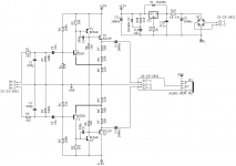
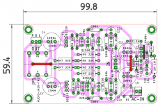
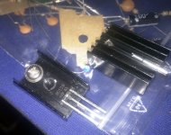
Have updated the schematic according to the suggestions and renamed components according to the first post. The PCB is still not final, may change it later. Got some of the parts. Only few resistors missing. Also found small heatsink. I think these might do the job.
Further suggestions / improvements are welcome.
Attachments
- Home
- Amplifiers
- Headphone Systems
- 3 Transistor HP Amplifier with low dist