B.t.w., this amplifier should have a catchy name 🙂

I named mine T3. Maybe not catchy but helps me remember what's inside 😉
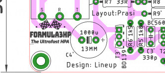
My suggestion is: Formula3HP
Because of the 3 transistors and HeadPhone.

Great to see this made into one of your PCBs Prasi. And interesting to see an AC input rather than DC-DC regulation. I'd be interested to see if it makes a difference using linear power rather than an SMPS.
Hello avtech,
Thanks..
just thinking out loud here.. would it do any good to put a 5-10mH choke at the power input when using smps? I think I had seen this in one of the DIYA hpa using smps power.
I always this EMI filter from AliExpress:would it do any good to put a 5-10mH choke at the power input when using smps?
Attachments

About the input capacitor = 22uF electrolytic
That cap was only used by me because sometimes my simulator measure correct only when is a high capacitance.
In reality I would recommend a film cap of value 2.2uF
That is quite alright for the input.
Those that can find a polyester or MKT of size 4.7uF can use this.
But as said, 2.2uF film cap will do perfectly.
This shows that cap:
Attachments
Last edited:
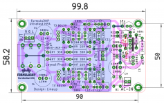
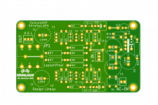
Finally happy with this version.
here 2.5mm, 5mm,7.5mm,10mm, 15mm pitch caps be fitted for C2, also small heatsink 274-1AB can be fitted for BD139. LM317 can go on bottom plate if required. In psu, RC/ CRC optional..
here 2.5mm, 5mm,7.5mm,10mm, 15mm pitch caps be fitted for C2, also small heatsink 274-1AB can be fitted for BD139. LM317 can go on bottom plate if required. In psu, RC/ CRC optional..
Attachments
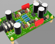
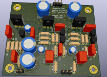
@prasi and @joensd
Your beatiful work makes me happy.
It is fantastic 🙂
All the best to India and Germany from me in Sweden
Your beatiful work makes me happy.
It is fantastic 🙂
All the best to India and Germany from me in Sweden
Thank you and Namaste!Thanks joe, your pcb is looks nice. All the best for your build.
Namaste to sweden too!Your beatiful work makes me happy.
If this makes us all happy it´s a win-win
and if the amp sounds half as good as it simulates I´ll indeed be very happy.
I think it would me much easier to adapt/use the circuit with 9V at least
but I´m sure lineup has a more eloborate answer for you.
Can you get hold of a ~12VDC wall wart? (AC would work too with Prasi´s circuit)
A little DCDC-converter that converts your 5V to 12V would be a good option too but it would need about 0.5A from your 5V supply.
What´s the impedance of the heaphones you wann a drive with it?
The headphones are 32 ohms. I have a USB DAC that's powered by a 5V linear PS. It would be nice to include this simple 3 transistor head amp in there.
I am thinking of a veroboard point-point implementation.
I am thinking of a veroboard point-point implementation.
Just remember if you are feeding a LM317 regulated circuit, you need to supply about 4v above the regulated voltage.
For a 5v (or 9v) circuit, you'd probably be ok with just a simple CRC filter at the front.
As joensd suggested, a DC boost converter would be a good option to retain the PSU filtering and not have to change the amplifier circuit.
For a 5v (or 9v) circuit, you'd probably be ok with just a simple CRC filter at the front.
As joensd suggested, a DC boost converter would be a good option to retain the PSU filtering and not have to change the amplifier circuit.
Last edited:
Hi Lineup,
Can this circuit be adapted for a 5V supply?
I think it would me much easier to adapt/use the circuit with 9V at least
but I´m sure lineup has a more eloborate answer for you.
Can you get hold of a ~12VDC wall wart? (AC would work too with Prasi´s circuit)
A little DCDC-converter that converts your 5V to 12V would be a good option too but it would need about 0.5A from your 5V supply.
What´s the impedance of the heaphones you wann a drive with it?
Circuit can be adapted for 9V, but probably not 5V.
But if you are using 9V battery - there is a big problem: Circuit draws 100 mA.
That would empty battery quickly.
Best is to use 12VDC with a LM317 regulator.
For 9V regulator we need to change some components values.
DC-DC Boost adjustable Converter XL6009 Module | eBay
XL6019 DC-DC 4A Boost Power Supply Module 3V~32V To 5V~35V Adjustable Converter 699930805801 | eBay
Was think about similar converters to the above.
Should work reliably enough at 5V/0.5A and it would make sense if you already have a 5V-supply that can spare 0.5A.
I´d still follow that with at least some RC-filter. Another voltage regulator is probably not needed.
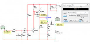
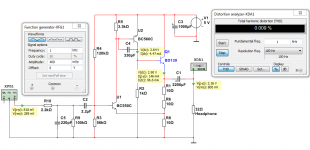
Here is one version for 5V.
It should work eventhough the dist is a litter higher.
THD 0.009% instead of 0.001%
It is possible someone could tweak this 5V version further.
But the distortion is still very small for this version.
The gain is here x3. The original has x4.
It should work eventhough the dist is a litter higher.
THD 0.009% instead of 0.001%
It is possible someone could tweak this 5V version further.
But the distortion is still very small for this version.
The gain is here x3. The original has x4.
Attachments
- Home
- Amplifiers
- Headphone Systems
- 3 Transistor HP Amplifier with low dist