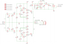
That´s an LM317 or similar you´re using, right?
Did you forget the wire from between R20&C12 to the ADJ-pin?
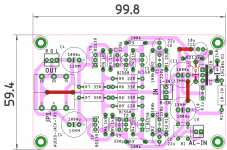
Thanks for your beautiful layouts BTW.
They are a joy to study and look at!
Yes, eagle eyes you have...
Thanks BTW...
Attachments
@prasi
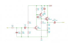
Beautiful schematic.
It also have the correct components as recommended.
But R3 should be 180k
Beautiful schematic.
It also have the correct components as recommended.
But R3 should be 180k
Last edited:
Great to see this made into one of your PCBs Prasi. And interesting to see an AC input rather than DC-DC regulation. I'd be interested to see if it makes a difference using linear power rather than an SMPS.
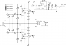
I have a few TIP41C transistors left, a bit too much power but can they replace the BD139 ones if needed?
I think you can use TIP41C.
It will give a little more distortion.
But as there is a feedback the different will not be dramatical.
It will give a little more distortion.
But as there is a feedback the different will not be dramatical.
Thanks Lineup!I think you can use TIP41C.
It will give a little more distortion.
But as there is a feedback the different will not be dramatical.
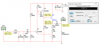
I did a testrun simulation with TIP41C.
The result is just the same as BD139 = THD 0.001%
See image.
So there is not at all problem using TIP41C.

B.t.w., this amplifier should have a catchy name 🙂
Last edited:
Something like this ,
https://www.mouser.in/ProductDetail/Diodes-Incorporated/DF10M?qs=G5AQjGfRJcIrwPKN/iDgDw==
It's B- Dil package of rectifier
https://www.mouser.in/ProductDetail/Diodes-Incorporated/DF10M?qs=G5AQjGfRJcIrwPKN/iDgDw==
It's B- Dil package of rectifier
Just sold a headphone amplifier and don´t really need another one
but the force is strong with this one!
And it simulates just so well.
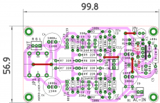
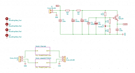
Made a little sunday afternoon layout.
2-layers with brute-force GND on both layers.
RC-filters and TL431+pass transistor cause its just another BD139. (the TL431-circuit is from FauxFrench!)
Probably find me a tiny aluminium stripe and attach the transistors to it. (attach insulated!)
If anybody in germany wants some PCBs we could share. I probably only need 2 PCBs.
but the force is strong with this one!
And it simulates just so well.
Made a little sunday afternoon layout.
2-layers with brute-force GND on both layers.
RC-filters and TL431+pass transistor cause its just another BD139. (the TL431-circuit is from FauxFrench!)
Probably find me a tiny aluminium stripe and attach the transistors to it. (attach insulated!)
If anybody in germany wants some PCBs we could share. I probably only need 2 PCBs.
Attachments

B.t.w., this amplifier should have a catchy name 🙂
I named mine T3. Maybe not catchy but helps me remember what's inside 😉
🙂 I agree with Joensd "the force is strong with this one".I named mine T3. Maybe not catchy but helps me remember what's inside 😉
How about ¨The Force"? 😀
Just sold a headphone amplifier and don´t really need another one
but the force is strong with this one!
And it simulates just so well.
Made a little sunday afternoon layout.
2-layers with brute-force GND on both layers.
RC-filters and TL431+pass transistor cause its just another BD139. (the TL431-circuit is from FauxFrench!)
Probably find me a tiny aluminium stripe and attach the transistors to it. (attach insulated!)
If anybody in germany wants some PCBs we could share. I probably only need 2 PCBs.
Why stop at one.. I've got 2 made at the moment with parts for 10 available... 😱
It simulates well but sounds even better!
Thanks for sharing the a version the FauxFrench's circuit. I think I'll give that one a go too!
Hi joensd, would be in with one or two. Cheers, ErnstJust sold a headphone amplifier and don´t really need another one
but the force is strong with this one!
And it simulates just so well.
Made a little sunday afternoon layout.
2-layers with brute-force GND on both layers.
RC-filters and TL431+pass transistor cause its just another BD139. (the TL431-circuit is from FauxFrench!)
Probably find me a tiny aluminium stripe and attach the transistors to it. (attach insulated!)
If anybody in germany wants some PCBs we could share. I probably only need 2 PCBs.
Good idea!How about ¨The Force"? 😀
My simulation files have the suffix 3QA (3 Transistors, Class A).
Or maybe R9Q3 (9 resistors, 3 Transistors).
I´ll call mine R9Q3-LUFFJD (short for: schematic: lineup, PSU: FauxFrench, Layout: Jens D.).
If anybody wants to use the gerber files: I want to update them later.
There was too big an interruption in the bottom layer ground plane that I got rid of and placed more vias.
I literally just ordered 2 other designs from JLCPCB.Hi joensd, would be in with one or two. Cheers, Ernst
Have an upcoming project where I´ll probably order in 2-3 months and maybe include this lineup-design then?
If you should order before me, count me in for 2PCBs. They can be easily shipped in a letter for 0.80€.
JLCPCB costs probably 2$ for 5 PCBs plus 7$ shipping.
I´ll let you know if I change my mind and order anyway. (the force!)
Last edited:
The TL431-circuit was suggested by FauxFrench in our amplifier project.Thanks for sharing the a version the FauxFrench's circuit. I think I'll give that one a go too!
We needed a ~+-15V supply for one opamp (from +-42V) and that is what FauxFrench came up with:
TL431 and pass-transistor for negative voltages.
- Home
- Amplifiers
- Headphone Systems
- 3 Transistor HP Amplifier with low dist