Sooo... Due to being sick had some time....Okay.
🙂 Stefan
Was really a grounding problem.... Doublechecked the star grounding and found an error...
wellVery nice amp, @lineup! Congratulations!
Two easy ways of bringing the distortion further down:
View attachment 1139665
Red - bootstrap the load of the 2nd BJT.
Green - replace the Miller capacitor around the 2nd BJT with a different compensation (trim the resistors in the two RC networks for best square wave response).
Attachments
Hi @lineup,Here we go.
The result is quite alright. Distortion is only 0.002%. This is a very clean sound.
LM7815 is good enough and easier to use than LM317.
Transformer should be a small 15VAC. Because the circuit does not draw much current.
Adjustment is to set the output of BD139 at 9.00 Volt. As seen in the schematic.
All resistors are 0.6Watt. This is because of the fairy low current in output.
I will be waiting for some pictures of your amplifier when is done.
Can you please simulate a n-jfet input in the 15V version? I have some jfets lying around...

Hi all!
I want to make the v3 for 72 ohm headphones.
What do I actually control with R11 and how much should be set? Sorry for the lame question🙄
I want to make the v3 for 72 ohm headphones.
What do I actually control with R11 and how much should be set? Sorry for the lame question🙄
R11 - quiescent current control
I have both resistors of 75 ohms
headphones - Amiron Home (250 Ohm)
I have both resistors of 75 ohms
headphones - Amiron Home (250 Ohm)
What kind of headphones do you have?Hi @lineup,
Can you please simulate a n-jfet input in the 15V version? I have some jfets lying around...
What is the impedance? Ohms?
And what JFETs?
Thanks.
I will do a simulation and suggest a working circuit.
I will try to finish today or tomorrow.
Do you have BD139 ?
I will do a simulation and suggest a working circuit.
I will try to finish today or tomorrow.
Do you have BD139 ?
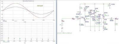
At first I made an amplifier with BD139 as output device.
But then I made this amp with IRF510 as output.
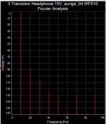
This circuit has a tiny bit more distortion, but the distortion is mainly 2nd harmonic. See image.
Which make me think this circuit will 'sing' better.
You should adjust with the potentiometer to get 8.00V at the output.
If this is not possible you may need to change R4.
There are four resistors in output. All 22 Ohm.
They all can be 1/2Watt or 0.6Watt.
I have used BC560C for U1. But this can be any PNP Small Signal transistor. For example 2N5401 or other.

But then I made this amp with IRF510 as output.
This circuit has a tiny bit more distortion, but the distortion is mainly 2nd harmonic. See image.
Which make me think this circuit will 'sing' better.
You should adjust with the potentiometer to get 8.00V at the output.
If this is not possible you may need to change R4.
There are four resistors in output. All 22 Ohm.
They all can be 1/2Watt or 0.6Watt.
I have used BC560C for U1. But this can be any PNP Small Signal transistor. For example 2N5401 or other.
Attachments
Using HPA3 happily for almost three years now I finally found out why the volume potentiometer made scratchy noises. Two new volume potentiometers later I saw This post suggested using 1nF to ground placed just before the volume pot. And that mysteriously solved the problem.
According to that post: "The reason for the cap in bipolar input devices is that the input bias current causing ‘scratchy’ noise as you adjust the pot level."
However I do not know how a capacitor to ground can change the input bias current (if I interpreted that correctly)...
Without using that 1nF capacitor, if I disconnected the source ( DAC) the problem was gone. Did it have something to do with my DAC?
you could try a different source like mobile phone / CD player and see if the noise is still there.
even i have seen builds with 1nF cap to chassis right at RCA binding posts.
i had faced this issue with normal pots, but changing to make-before-break step pots solved the issue for me.
even i have seen builds with 1nF cap to chassis right at RCA binding posts.
i had faced this issue with normal pots, but changing to make-before-break step pots solved the issue for me.
I built it. It produces a clean sound, but I find the low frequencies a bit too strong and the crisp, fast high frequencies somewhat lacking. Could it be that C2 with 2.2µF is too much? It forms a high-pass filter with R4, whose cutoff point is 1.4Hz, while C4 (2200µF) with the 72-ohm headphones results in 1Hz.OMG😱
You saved me from a major fiasco. Thanks avtech🙂.
I request moderators to delete post #150.
here are correct files.

As a test, I will try reducing C2 to 220nF, increasing R4 to 150kΩ, setting R3 to 330kΩ, R5-6 to 1kΩ, and C4 to 470µF. This way, the lower cutoff frequency will be around 5Hz, and the response time might improve. The current of T3 will be approximately 60mA.
main issue with these designs is unequal clippingFormula3HP
Here is an Amplifier using 3 transistors.
It has low distortion.
Gain is x4 which should be good for 32 Ohm headphones.
Power supply could be one LM317 set at 12 VDC.
All resistors can be 0.6 Watt.
Formula3HP
The latest version is in https://www.diyaudio.com/community/...p-amplifier-with-low-dist.359267/post-7055776
Only an issue if you regularly run an amp into the clipping region, which isn't really recommended..
- Home
- Amplifiers
- Headphone Systems
- 3 Transistor HP Amplifier with low dist