Which wattage should the fransformer have ?
And about a volume pot. Which one would you recommend ?
And about a volume pot. Which one would you recommend ?
I’m not Lineup, but I didn’t see an answer to this yet. Anyway, it filters out some of the power-supply ripple, so less of it ends up getting fed into the amp. Using jargon, it improves the power supply rejection ratio (PSRR).Hey Lineup, what is the point of C6? Removing it doesn't seem to do anything in the sim...
Love this amp, but haven’t soldered it up yet. Other projects in the queue ahead of it!
It was answered in the post directly following that one:
https://www.diyaudio.com/community/...p-amplifier-with-low-dist.359267/post-7036705
https://www.diyaudio.com/community/...p-amplifier-with-low-dist.359267/post-7036705

What schematic do you refer to?Hey Lineup, what is the point of C6? Removing it doesn't seem to do anything in the sim...
Most probably that cap is like it is said: Filter supply to achieve better PSRR. Power supply rejecting ratio.
Now if you have a clean and good supply, there is not so much need for that cap.
For example if you use LM317 to regulate voltage.
Last edited:
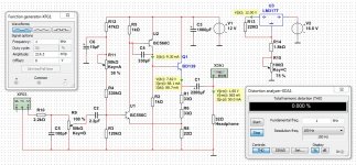
Thank you Lineup!Here I post the latest schematic of 3-transistor amplifier I have.
Suitable transformer is 12VAC when used with LM317.
When you rectify such a transformer you get like 17VDC or even a bit more.
The add LM317 to get 12.0 Volt supply.
I noticed the filter at the input consisting of R10 and C5 is not necessary but C4 highly likely is. What is your opinion about this?
Both are necessary - the input filter (R10-C5) is a low pass to ensure the amp doesn't get HF and oscillate. I added C4 experimentally when first building Lineup's design because I found the amp was unstable without 220-330pF. It may have been down to the layout so if you have an oscilloscope, you can always test different values or omit and see how it behaves.
Hi Avtech. I do not have an oscilloscope to verify whether it is oscillating or not but it is my impression the input filter can be left out because of the use of C4. Anyway, so far so good without the input filter 🙂Both are necessary - the input filter (R10-C5) is a low pass to ensure the amp doesn't get HF and oscillate. I added C4 experimentally when first building Lineup's design because I found the amp was unstable without 220-330pF. It may have been down to the layout so if you have an oscilloscope, you can always test different values or omit and see how it behaves.
You can do it without any component that you consider useless. 😎
It is your choice and no one can convince you. In fact, it is a bad thing to impose your own opinions on someone who thinks differently.
It's freedom!!! 🥳🤩🥳
It is your choice and no one can convince you. In fact, it is a bad thing to impose your own opinions on someone who thinks differently.
It's freedom!!! 🥳🤩🥳
Haha of course Knauf1919! Just curiousYou can do it without any component that you consider useless. 😎
It is your choice and no one can convince you. In fact, it is a bad thing to impose your own opinions on someone who thinks differently.
It's freedom!!! 🥳🤩🥳

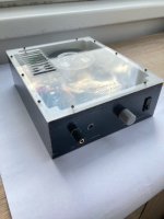
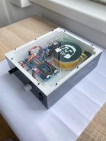
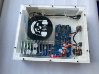
This is my latest project. I'm implemented the amplifier to XIAO DAP (by @blue__seven) project

the amp is use 9v from boost converter

the amp is use 9v from boost converter
Nice project!This is my latest project. I'm implemented the amplifier to XIAO DAP (by @blue__seven) project
View attachment 1096218
the amp is use 9v from boost converter
View attachment 1096219
Can you share some details of the DAC?
Is it possible to DIY such a DAC?
ThanksNice project!
Can you share some details of the DAC?
Is it possible to DIY such a DAC?
the DAC is TDA1387 (nxp) with simple JFET I/V, i2s signal buffered by 74hc125.
TDA1387 is common used as DIY DAC project.
Ok. Thank youThanks
the DAC is TDA1387 (nxp) with simple JFET I/V, i2s signal buffered by 74hc125.
TDA1387 is common used as DIY DAC project.
Same schematic for 300 ohms headphones?Here I post the latest schematic of 3-transistor amplifier I have.
Suitable transformer is 12VAC when used with LM317.
When you rectify such a transformer you get like 17VDC or even a bit more.
The add LM317 to get 12.0 Volt supply.
Sorry to kept you waiting.Same schematic for 300 ohms headphones?
Now I am working on a 300 Ohm version.
It will be posted here.
What transformer do you have?
I am planning using an 15VAC transformer, as 300ohm needs a bit more voltage but less current.
The regulated voltage will be 15VDC.
If you have already a 12VAC transformer I make the circuit for that.
Last edited:
- Home
- Amplifiers
- Headphone Systems
- 3 Transistor HP Amplifier with low dist