
I am building a simple source follower a la Nelson pass for a compression driver and thought I should add a preamp just in case I want to use the PCB as headphone amp or for a less sensitive tweeter. (Nelson´s simple follower)An variant with IRF610 would also be interesting.
I tried with 1x or 2x 2SK117GR but 2xBJT always give me much better distortion values in sim than a FET preamp.
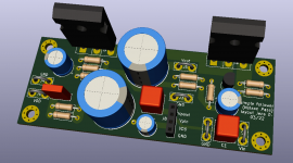
Current plan is to make a compact PCB for the follower and include an optional vertical PCB for the preamp in order to play with different implementations.
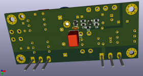
Made PCB-mockups with the 2BJT´s in SMD too.
If low distortion incl. H2 is your ultimate goal I´d stick with lineup´s designs though.
Attachments
Just for inspiration. No final PCBs and actually not sure if I will ever get any of these produced.
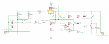
1. Simple follower with optional preamp card (on perfboard or so)
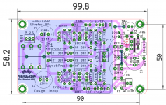
2. Simple follower with 2xBJT-preamp in SMD on the bottom layer.
1. Simple follower with optional preamp card (on perfboard or so)
2. Simple follower with 2xBJT-preamp in SMD on the bottom layer.
Attachments
Hello carageae@, i have external linear supply 2X25V dc feeding 2X Denoiser, one pcs for channel. I use Prasi`s HPA Fast pcb. I cut one trace that i can use 2 X Denoiser.Hello! Can you post the exact schematics of amp and supply used? I also have build two versions of this amp and own HE400SE. The Denoiser is knauf1919's project? Which transformer and capacitors used in the Denoiser?
Attachments

Hi, joensd
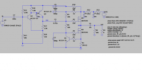
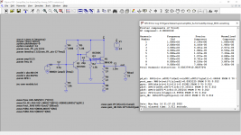
Can you do a simulation with BC556 / 546 instead of 550/560 and then post a diagram with some voltage / current values in the essential parts?
Thanks.
Can you do a simulation with BC556 / 546 instead of 550/560 and then post a diagram with some voltage / current values in the essential parts?
Thanks.
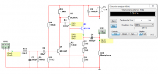
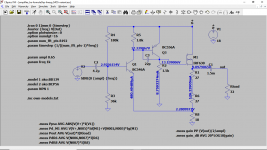
Here you go (used "A" types from Philips for the transistors ; there is also B types).
Just consider this is probably still not the best it can be!
For higher impedance headphones bias could be lowered of course.
Watch the power dissipation of the source resistors!
R1&R6 (2x27R) could be 1x56R/2-3W-type for example.
R8 could still be a 0.6W-type but right at the edge with 0.3W of dissipation.
Attachments
does it have any sense against simple TDA2030 loaded to 150 mA current source (biased toward class-A operation) ??
I regularly listen to a TDA2009, much better than 2030...I made an amplifier with higher negative feedback, specially suited for headphone use.does it have any sense against simple TDA2030 loaded to 150 mA current source (biased toward class-A operation) ??
But let's stick to the original thread...
How does it sound, psycho-acusticaly, compared to BD139 version? Is there some change in the sound signature?
I'm thinking of using Prasi's PCB with built in rectifier/regulator.
Would I be correct in thinking a 14V AC input would be optimal?
Would I be correct in thinking a 14V AC input would be optimal?
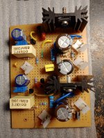
Fitted a beefy power supply, with 9400uF + 2 RC filters before the regulator. Sounds good, with crystal clear highs and good instrument separation.
Brought down the gain by using 10R + 20R resistors. Plenty loud for my headphones.
Thanks Lineup.
Brought down the gain by using 10R + 20R resistors. Plenty loud for my headphones.
Thanks Lineup.
The latest version of pcb. I'm moving on to another project as good or better. 🤓


- Home
- Amplifiers
- Headphone Systems
- 3 Transistor HP Amplifier with low dist