Does anyone have suggested improvements for a low-gain version?
-------
@jasonRF
I have done experimenting in SPICE. I tested replacing R7 with a current source.
For my setup here it was best with 1.70mA.
Such a CCS you can easily do with two 2N3904.
The benefit is a bit lower distortion.
Of course this will be a 5T amplifier 🙂
-------
@jasonRF
I have done experimenting in SPICE. I tested replacing R7 with a current source.
For my setup here it was best with 1.70mA.
Such a CCS you can easily do with two 2N3904.
The benefit is a bit lower distortion.
Of course this will be a 5T amplifier 🙂
Attachments

Hi Lineup,
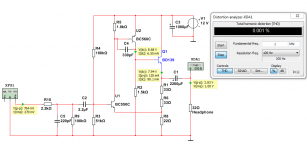
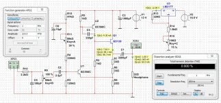
I tried the two resistor changes: replaced 120k with 180k, and 1.8k with 2,7k. For 800mV peak into a 33Ohm resistor (~10 mW) ,I get the attached measurent, which is a significant improvement. The strange thing is that my LTSpice simulation predicted this change would make things worse, so my simulation has problems...
Thanks!
Jason
Hi Lineup,
I am out of 10 uF caps, so used 47 kOhm - 47 uF - 120 kOhm at input. Measurement attached is driving 800 mV peak into 33 Ohms. Holy Moley Batman!
I don't think the measurement is at all accurate since we are at the limits of the Scarlett Solo; the 2nd harmonic is significantly lower than what I see with a direct loop-back (which I just repeated 2 minutes ago) which seems bogus. And I re-did the posted measurement several times over 20 minutes and basically got the same thing every time...
In any case, the distortion is tiny, and of course we see the expected reduction in the mains bleed-through. The weird thing is that this measurement is from the side that was worse yesterday, while the previously-better-side isn't as happy now. Perhaps the 30-year-old breadboard isn't so reliable anymore, or perhaps I bumped some parts with my klutzy fingers, or ... Not much needs to go wrong to effect things more than 100 dB down!
Anyway, I think I need to solder it up to really tell what I have here.
Cheers!
jason
I would not recommend the original circuit for 250, 300 and 600 Ohm headphones.Hello lineup@, neat circuit👍 how this circuit work with 250ohm cans?
250 needs more gain.
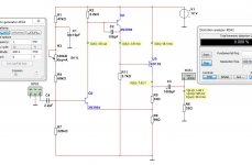
So, I have made a version for 250 or higher headphones. With gain x4. Using four 15ohm resistors.
The power supply should always be LM317T.
Attachments
Sorry.
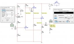
The original circuit has a supply of 12VDC and gain is x4.
So, the original circuit should work with 250 ohms headphones.
This is the original circuit:
The original circuit has a supply of 12VDC and gain is x4.
So, the original circuit should work with 250 ohms headphones.
This is the original circuit:
Attachments
Last edited:
Thank you lineup🙂Sorry.
The original circuit has a supply of 12VDC and gain is x4.
So, the original circuit should work with 250 ohms headphones.
This is the original circuit:
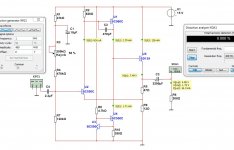
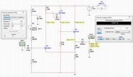
This is a new, revised Version.
It has slightly better data and shows also LM317T for the 12V supply.
I think it should work with 32 Ohm and 250 Ohm, too.
Probably needs a change for 300 and 600 Ohms headphones.
It has slightly better data and shows also LM317T for the 12V supply.
I think it should work with 32 Ohm and 250 Ohm, too.
Probably needs a change for 300 and 600 Ohms headphones.
Attachments
Last edited:
Thanks👍This is a new, revised Version.
It has slightly better data and shows also LM317T for the 12V supply.
I think it should work with 32 Ohm and 250 Ohm, too.
Probably needs a change for 300 and 600 Ohms headphones.
Excellent work🙂 Thanks.Here is the recommended version for 250ohm - 300ohm - 600ohm.
I really think this is best with 18V supply and a 2x18VAC trafo.
Hello! Can you post the exact schematics of amp and supply used? I also have build two versions of this amp and own HE400SE. The Denoiser is knauf1919's project? Which transformer and capacitors used in the Denoiser?Hello all, i made 12V version of this amp and Denoiser regulator. Testing 25ohm Hifiman HE400SE. Oh boy this sounds so holographic.
Thanks lineup!!!
- Home
- Amplifiers
- Headphone Systems
- 3 Transistor HP Amplifier with low dist