To get space for the electrolytic capacitor you can make some changes. I hope it is understood from the ticks in the drawing.
knauf1919 thanks for the suggestion, it's quite clear..
tried a lot but it's something like a sliding puzzle,
after a point it can't get any tighter.
maybe changing the layout helps..
i may try again when works get a little easier 😉
Imo there is a trade-off between compactness and maintainability. Perhaps you could make things more compact by building 3D (stacking components) but it makes troubleshooting a lot more difficult if not impossible without damaging the pcb and/or components.
Imo there is a trade-off between compactness and maintainability. Perhaps you could make things more compact by building 3D (stacking components) but it makes troubleshooting a lot more difficult if not impossible without damaging the pcb and/or components.
totally agree with you. also unnecessarily closer components same either..
nevertheless tightened up the last bits of available space and enlarged the output caps to the 16mm.. although it looks pretty ugly, i think i should stop here..
Attachments
knauf1919, thank you so much..
it's too hard to repeat/mirror this on the right side because of the switch which i want to keep..
i tried some more layouts including smd but decided to order last design above. it's quiet simple and decent to me.
btw, you must have overlooked, C4 should be connected between collector and base legs on bc560c..
Attachments
Sorry, I wasn't careful. It's just a small demonstration that it can be improved. Even on the other side.
just realized that, there is a big mistake on all my layouts;
R5 must be connected to V+ NOT Ground!
my apologies..
R5 must be connected to V+ NOT Ground!
my apologies..
Built one based on prasi layout.
had to change a few resistors and capacitors as they weren't available.
330pF -> 470pF
51K -> 56K


It works, no magic smoke. No significant DC offset as checked by my cheap volt meter.
The only thing is that the four 33ohm resistors are getting very hot. Finger burning hot and getting darker. is that because of 56K resistors ?
i have also got hither watt 33ohm, will replace them next. The transistor a just warm, hardly noticeable.
Edit: power section is not completed, had powered it from bench PSU which showed around 200mA on 12V.
had to change a few resistors and capacitors as they weren't available.
330pF -> 470pF
51K -> 56K
It works, no magic smoke. No significant DC offset as checked by my cheap volt meter.
The only thing is that the four 33ohm resistors are getting very hot. Finger burning hot and getting darker. is that because of 56K resistors ?
i have also got hither watt 33ohm, will replace them next. The transistor a just warm, hardly noticeable.
Edit: power section is not completed, had powered it from bench PSU which showed around 200mA on 12V.
Good to see another one come alive!
It's a good idea to use 2 or 3 watt parts for the output resistors as they heat up less. Also it's a good idea to elevate them off the board to prevent heat damage and encourage airflow.
From memory I used 51k with 180k (instead of 56k and 191k) because 180k was easier to get. You may need to change the 180k back to 191k (or thereabouts) to maintain the intended circuit voltages.
I put five 2W resistors in parallel for the value of 66 Ohm. It's perfect.
You can only put four.

You can only put four.
Thanks for advise. Will replace the 33R with higher wattage but this board is very cramped.
Also if no jack is connected the outputs are shorted, i think i should isolate them.
And can please someone recommend relay based DC Protection and Delay (through hole components).

Also if no jack is connected the outputs are shorted, i think i should isolate them.
And can please someone recommend relay based DC Protection and Delay (through hole components).
You shouldn't really need DC protection on this because the amp has an output coupling cap - the cap blocks any DC from reaching the output.
I think it is better to switch the output through a couple of 1k 1/2w resistors rather than short it out. This allows the output caps to discharge when the amp is powered down and unplugged, and allows the headphones to be safely unplugged with the amp still powered up.
Personally I power on then plug in HP / unplug HP then power off, but even if I forget and just pull the power, the amp is polite enough and doesn't have a big thump.
Unless the shorting headphone jack is causing oscillation, I would leave it -- it's providing a valuable service by assuring that the output coupling capacitors are properly charged before the headphones are plugged in.
Cheers
edit: apologies to avtech23 -- his suggestion is probably better (but I'd already typed mine .. 😱)
edit2: if the heat coming off R7, R8 is still bothering you, maybe fashion a couple upside-down-'W's out of 15,18,15, and 18 ohm parts; same value, much improved airflow
Cheers
edit: apologies to avtech23 -- his suggestion is probably better (but I'd already typed mine .. 😱)
edit2: if the heat coming off R7, R8 is still bothering you, maybe fashion a couple upside-down-'W's out of 15,18,15, and 18 ohm parts; same value, much improved airflow
Last edited:
well.. another one come alive too! actually two..
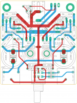
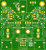
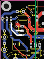
i did some more layout exercises and finally settled on this 60x60mm one..
when pcbs arrived, built immediately but got a huge 8.4V dc offset.
also realized that i did a silly mistake 😀
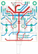
placed 220 pF caps as input capacitors (see the black circle on the layout )..
placed the caps underside of the input jack..
and changed the output capacitors but dc offset didn't gone.
then built another, 5V version, but it has same dc offset problem either..
according to this thread; https://www.diyaudio.com/community/threads/dc-offset-with-output-coupling-capacitors.310524/;
paralelleling 1K resistors to the load solved the problem partially..
when turn on, dc offset is there but within 10 seconds it settles on 0V..
5V version moderately warm but not getting hot.
but 12V version quite hot.. these are what measured on it;
BD139 > 45 °C
R1-R6 > 58 °C
R8 > 47 °C
BC550-560 > 37 °C
also when turn off, there is a sizlling sound on left channel only for 1-2 seconds on both amps, seems like a pcb layout problem.
besides these, they have a beautiful sound..
a natural timbre what i like most..
I would like to thank again to lineup and you guys who have helped me a lot..
edit: typo.


i did some more layout exercises and finally settled on this 60x60mm one..
when pcbs arrived, built immediately but got a huge 8.4V dc offset.
also realized that i did a silly mistake 😀
placed 220 pF caps as input capacitors (see the black circle on the layout )..
placed the caps underside of the input jack..
and changed the output capacitors but dc offset didn't gone.
then built another, 5V version, but it has same dc offset problem either..
according to this thread; https://www.diyaudio.com/community/threads/dc-offset-with-output-coupling-capacitors.310524/;
paralelleling 1K resistors to the load solved the problem partially..
when turn on, dc offset is there but within 10 seconds it settles on 0V..
5V version moderately warm but not getting hot.
but 12V version quite hot.. these are what measured on it;
BD139 > 45 °C
R1-R6 > 58 °C
R8 > 47 °C
BC550-560 > 37 °C
also when turn off, there is a sizlling sound on left channel only for 1-2 seconds on both amps, seems like a pcb layout problem.
besides these, they have a beautiful sound..
a natural timbre what i like most..
I would like to thank again to lineup and you guys who have helped me a lot..
edit: typo.
Congrats endia! Well done -- 
Everything but the 'sizzling' sounds very normal -- the large output capacitors need a DC return path. If the headphones don't provide it (ouch!), the caps' leakage will keep the voltage across it low, and DC ('alleged', because any small current will drain it) on the output connector. This is not the same 'problem' as an ~8V offset on the output of a class AB or D amp with bi-polar power supplies.
The hiss is interesting, though. Do you own / could you borrow an oscilloscope? Where did the 220pF capacitors end up? Do you still have the small capacitor placed across the VAS transistor, Q2? (edit🙂 C4, 330pF -- what flavor is it, MLC / ceramic / C0G ?
You do have an uncomfortably large loop area to the higher-current output path. Is there a big AM broadcast transmitter nearby, maybe?
The 220pF caps you're showing in the black circle are in series with the incoming signal -- that won't work. Not positive, but methinks they belong in parallel with the R9's. That combined with the 2k2 series resistors gives the RF rejection every amp desires.
Still, a very nice bit of work; and I REALLY like the high power resistors out on the perimeter!
Regards
Last edited:
Rick, thank you very much
I didn't placed 220 pF caps on there, realized the mistake and placed on the legs of input jack underside of the board.. they can be paralled with R9s but didn't want to place them after pot.. Lineup was suggested to place them before the pot in the very early posts..
Both 220 pF and 330pF caps are multi layer ceramic.. I have not an oscilloscope and also have no idea where to borrow one unfortunately..
It's possible that there is a lot of signal/transmitter around because we moved into this house from a relatively quiet place last year and I can't listen to the tuner anymore due to too much interference. But i have a couple of amps too (szekeres, ppa etc.) but none of them have this kind of problem.. maybe due to large loop area on the output path you mentioned..
Regards..
- Home
- Amplifiers
- Headphone Systems
- 3 Transistor HP Amplifier with low dist