Hi Toni,
Could you explain/show how you do MOSFET matching? I am not sure what is best simple way to do that.
BR Damir
"Papa" Pass has a very good explanation how to do this @home:
http://www.firstwatt.com/pdf/art_mos_test.pdf
BR, Toni
A current limiter is not an impedance/resistance measuring circuit.
Never said that.

LTSpice2PCB / beta testers
Forward annotation works!
pcb/geda specific values can be directly inserted in your ltspice schematic as comments like attached picture.
Beta testers wanted.
You need following software installed:
BR, Toni
...
Regarding LTSpice2PCB: I have good news for you! Today I have written a perl program which is able to read a LTspice "asc" and LTspice "WireList netlist" file and generates a BOM (first step) and a pcb/geda readable part/netlist file (2nd step - needs BOM file with added footprint data).
Generated BOM with added footprint and pin renumbering data looks currently like:D13 zener diode_zener_rm2.54 <remap> Z15Fields are delimited by "TAB". Field number 1,2,5 are provided by converter program, field 3 and 4 is "footprint" and "pin reordering" (e.g. ebc, cbe or 3,1,2). A newer version could contain footprints as comments in the asc file (e.g.: "; footprint Q3=TO126_FLAT").
L1 ind diode_zener_rm2.54 <remap> 0.8µ
L2 ind diode_zener_rm2.54 <remap> 1.4mH
L3 ind diode_zener_rm2.54 <remap> 10mH
L4 ind diode_zener_rm2.54 <remap> 0.33mH
M1 nmos TO247AC gds IRFP240Ckst
M2 pmos TO247AC gds IRFP9240Ckst
M3 nmos TO247AC gds IRFP240Ckst
M4 pmos TO247AC gds IRFP9240Ckst
M5 nmos TO247AC gds IRFP240Ckst
M6 pmos TO247AC gds IRFP9240Ckst
Q1 pnp TO92-KL cbe BC560C
Q2 pnp TO92-KL cbe BC560C
Q3 npn TO126_FLAT ecb KSC3503
Pin number conversion is also done automatically for npn, pnp, njf, pjf,nmos,pmos,polcap,diode ...
Simple variables will be expanded too (e.g.: {Rbias} will be replaced by the latest active .param statement).
LTspice2PCB forward annotation is currently untested but may work too.
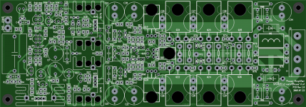
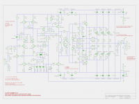
Attached a successful imported asc file from the current 50W MOSFET amplifier (footprints are not always the correct one - was only for 1st test)
If there is some real interest I will provide this as an opensource toolkit.
BR, Toni
Forward annotation works!
pcb/geda specific values can be directly inserted in your ltspice schematic as comments like attached picture.
Beta testers wanted.
You need following software installed:
- PCB/Geda version >= pcb-20140316
- perl >= 5.8.7
BR, Toni
Attachments

A bit on topic and off 😉
Pledge: http://www.diyaudio.com/forums/swap-meet/277395-wnt-astx-pcb-set-sa2014-rev-3-4-2-a-new-post.html
Regards
Pledge: http://www.diyaudio.com/forums/swap-meet/277395-wnt-astx-pcb-set-sa2014-rev-3-4-2-a-new-post.html
Regards
Gerber files for sa2014 and sa2015 PCB's
Where are the Gerber files for the latest version of the sa2014 and sa2015
PCB's?😕 Or is anyone going to do a Group Buy for these AMPS?😕
Where are the Gerber files for the latest version of the sa2014 and sa2015
PCB's?😕 Or is anyone going to do a Group Buy for these AMPS?😕
Where are the Gerber files for the latest version of the sa2014 and sa2015
PCB's?😕 Or is anyone going to do a Group Buy for these AMPS?😕
See also index in first post!
For SA2014/400W rev 3.4.2 amplifier (partially old name is SA2013) you will need:
- Latest valid PCB gerber files for input/VAS and output stage board can be found in post # 979 and 980
- PCB gerber files for power supply for one channel in post # 993
- Latest schematic in post # 1145 and corrected BOM in post # 1146
- R28 (100R) needs to be reduced to 68R to get some extra PM stability.
- "asc" files can be found in post #1149
SA2015 is in development and there exists no final schematic nor pcb gerber files.
BR, Toni
Toni, have you ever given thought to modifying the IPS/VAS for balanced input?
If balanced inputs are needed I would recommend to add an opamp powered instrumentation amplifier in front of the input/VAS stage.
SA2014 needs a preamplifier with low output impedance for best performance.
BR, Toni
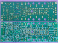
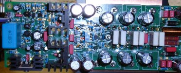
2stageEF 50W MOSFET - aka SA2015MT
... works out of the box 🙂🙂🙂 without holy smoke
at a maximum of 1% THD+N, bw 80kHz:
overall THD+N < 0.004% from 20Hz - 20kHz, bw 80kHz
BR, Toni
... works out of the box 🙂🙂🙂 without holy smoke
- Quicktest with +/- 42V regulated power supply
- Bias 450mA (150mA per mosfet)
at a maximum of 1% THD+N, bw 80kHz:
- max. 82W RMS output power 8R load
- max. 145W RMS output power 4R load
overall THD+N < 0.004% from 20Hz - 20kHz, bw 80kHz
- 50W RMS output power 8R load
- 100W RMS output power 4R load
BR, Toni
Attachments
Hi Toni,
As always, well executed and looks good. Look forward to see your further progress.
I need to get myself started and building an amplifier for bas duty in an active system. So if you come by some more spare-time and energy, please send some my way. 😀 I actually plan to use IRFP240/IRFP9240, but toying with the idea of a fully balanced design for the fun of it.
Cheers,
Mogens
You are welcome! More measurements will follow if I find some extra spare time ... 😉
Good luck for your project - maybe you find some spare time too ...🙂
BR, Toni
Good luck for your project - maybe you find some spare time too ...🙂
BR, Toni
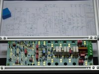
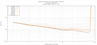
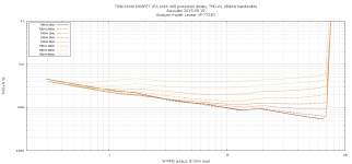
2stageEF 50W MOSFET - aka SA2015MT
... want more measurement data?
... want more measurement data?
- +/-42V regulated power supply.
- bias 450mA (150mA per MOSFET)
- slew rate > 90V/µS with input filter in situ
- 8R resistive load, bw 80 kHz
- no VAS protection diode installed
- 104 db full bw
- 111 dB 80kHz bw
- 119 dB A weighted
Attachments
Last edited:
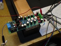
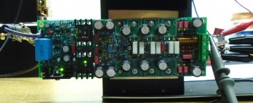
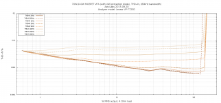
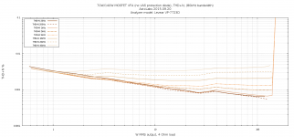
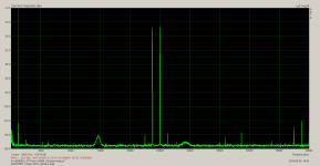
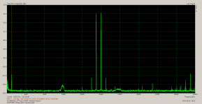
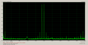
2stageEF 50W MOSFET - aka SA2015MT
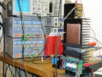
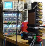
... attached 4R resistive load measurements.
THD+N measurements of output power above 120W@4R where not always possible due to current limiter of regulated power supply.
Right picture views current consumption on 10kHz / 140W / 4R output power test. Total power delivered by power supply ~ 240W
BR, Toni
Attachments
-
sa2015_thd+n_with_vas_protection_diode_4r.txt7 KB · Views: 159
-
sa2015_thd+n_no_vas_protection_diode_4r.txt6.9 KB · Views: 164
-
 sa2015_140w_4r_meas.jpg339.3 KB · Views: 331
 -
 sa2015_thd+n_with_vas_protection_diode_4r.png106.1 KB · Views: 257
 -
 sa2015_thd+n_no_vas_protection_diode_4r.png95.2 KB · Views: 628
Last edited:
2stageEF 50W MOSFET - aka SA2015MT
IMD measurements
No VAS diode installed:
0.0021% IMD @ 10Vpp @8R
0.0017% IMD @ 20Vpp @8R
0.0014% IMD @ 40Vpp @8R
0.0014% IMD @ 60Vpp @8R
IMD measurements
No VAS diode installed:
0.0021% IMD @ 10Vpp @8R
0.0017% IMD @ 20Vpp @8R
0.0014% IMD @ 40Vpp @8R
0.0014% IMD @ 60Vpp @8R
Attachments

IMD measurements
No VAS diode installed:
0.0021% IMD @ 10Vpp @8R
0.0017% IMD @ 20Vpp @8R
0.0014% IMD @ 40Vpp @8R
0.0014% IMD @ 60Vpp @8R
All really good results.😀
- Home
- Amplifiers
- Solid State
- 2stageEF high performance class AB power amp / 200W8R / 400W4R