Very nice "wolverine" , ASTX ! 😀
I'm kidding , but you are SO close (2 CCS's , EF for the cascode reference).
Your bias spreader is the same as the slew red LED referenced Vbe for the Vfet OPS.
Besides the CM "helper" 🙁 , I can just about assure you no "magic smoke"
out of your design , just <10ppm 20K !
Great work!
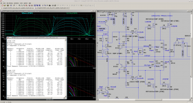
Edit - C12/C10 E. stuart recommends 4:1 - 5:1 ratio TMC ? I use 330/68pF ?
OS
Dear OS,
thx for your kind words. Would say 2StageEF/SA2013-SA2015 and Wolverine are both blameless derivates ... 😉
TMC/Cherry compensation was more or less a result of many iterative simulations hence the 10:1 ratio of the TMC capacitors. Without the Cherry component the ratio would be about 5:1.
BR, Toni
Can you verify this behaviour?
Problems on my LTSpice computer. Maybe hardware, unrepairable.
I will see what I can do, apart from curse Windows.
It may be that a non-helpered CM will require compensation to be retuned.
As I said, the same basics can work out to different results , often surprises me.
Best wishes
David
Phase margin of the global loop looks to be over 60°. This should be plenty, no?
Hi Harry,
Sorry to bring the thread back to this. Control loops are something that interest me. The question of how much PM/GM is enough isn't easy to answer in my opinion.
My current design has many loops (as per usual 😉). The two critical loops are the VAS and GNFB loops. To get good performance into unrealistic capacitive loads I need the VAS loop to have PM>100 degrees (GM isn't too critical) and the GNFB loop to have PM>60 degrees and GM>12dB.
When a 100nF (in series with 0.2R) load is directly attached to the amp output (before inductor) even at small output levels the PM in both loops is down to single figures. I can add a "magic" capacitor that significantly reduces the decay in PM. The penalty is another loop and a small increase in THD.
This suggests that there are more factors at play when assessing whether a given value of PM is enough for a given amp topology. This is where my understanding ends as to what these factors are...
Could a control loop be designed to be more resilient in the face of a capacitive load or are we governed by mathematics on this? Or could there be merit in adding a loop (like my magic cap) which is designed to mitigate the affects of a capacitive load on the overall amp.
Apologies for my ramblings and for the slightly OT post.
Best regards,
Paul
If you clobber the feedback loop to make the amplifier stable into capacitive loads, then you essentially just force the amplifier to perform the task of the usual L//R network. But the amplifier does it much less perfectly. A passive output network is almost always the best option.
Yes, phase margin is not a very enlightening way to understand oscillation into capacitive loads.
Yes, phase margin is not a very enlightening way to understand oscillation into capacitive loads.
If you clobber the feedback loop to make the amplifier stable into capacitive loads, then you essentially just force the amplifier to perform the task of the usual L//R network. But the amplifier does it much less perfectly. A passive output network is almost always the best option.
Yes, phase margin is not a very enlightening way to understand oscillation into capacitive loads.
You don't necessarily have to clobber the feedback loop too much just have to design for large stability margins. I remember your quest to design an amp fast enough not to need an output inductor. Indirectly, I've ended up on that quest too.
Agree with your other comments. I would always add an output inductor too but its nice to have good stability margins to begin with. It's the fear of parasitics in a real life circuit and my silly design methodologies.
Paul
Well, it depends on the type of compensation. They have different sensitivities to capacitive loads. Output inclusive miller compensation could probably be tolerant of capacitive loads, if you can make it stable. But some types of compensation force you to accept the output inductor as part of the stability compensation.
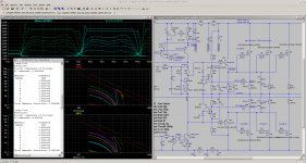
best SOA or best THD performance ...
Adding 1 more output pair helps a lot to get a good THD figure down to 3R load...
Adding 1 more output pair helps a lot to get a good THD figure down to 3R load...
Attachments
Last edited:
maybe I am not reading it correctly but you seem to be showing that adding a 3rd pair gives both better THD and better SOA.
Why does your header say "or"
D.Self (for BJTs) showed way back that adding an output pair results in significant lowering of distortion.
His "Load Invariant" paper was all about this.
Why does your header say "or"
D.Self (for BJTs) showed way back that adding an output pair results in significant lowering of distortion.
His "Load Invariant" paper was all about this.
Last edited:
maybe I am not reading it correctly but you seem to be showing that adding a 3rd pair gives both better THD and better SOA.
Why does your header say "or"
D.Self (for BJTs) showed way back that adding an output pair results in significant lowering of distortion.
His "Load Invariant" paper was all about this.
It is simply the same header/topic/title/paragraph where the two posts belong to. 😉
Of course you are right, that the second picture showed better THD and SOA headroom.
But I'm not sure, if the SOA protection is implemented correctly because I have removed the resistors in series with the Z-diodes due to very high distortion. More simulation tests have to be done...
BR, Toni
Hi Toni
Do you output your LTSpice simulation as a netlist and then import into PCB? I have started with D.Spark but wonder about other options.
Best wishes
David
Do you output your LTSpice simulation as a netlist and then import into PCB? I have started with D.Spark but wonder about other options.
Best wishes
David
I have been looking for an amp with this power. How far would it be from a possible pcb GB? Another dumb/lazy question - how low loads would be safe to load it with? Is it short proof? Anyone who have a link to fitting analog meters for this one - I know - bells and whissles but I'm a sucker for that kind of bling-bling 🙂.
Then of course I would need to have the right sized heathsink pointed out for me and probably others. Better to trust the ones knowing what they are doing 🙂.
When this seems to materialize in the real world - I will of course read the whole thread.
Regards
Then of course I would need to have the right sized heathsink pointed out for me and probably others. Better to trust the ones knowing what they are doing 🙂.
When this seems to materialize in the real world - I will of course read the whole thread.
Regards
I have been looking for an amp with this power. How far would it be from a possible pcb GB? Another dumb/lazy question - how low loads would be safe to load it with? Is it short proof? Anyone who have a link to fitting analog meters for this one - I know - bells and whissles but I'm a sucker for that kind of bling-bling 🙂.
Then of course I would need to have the right sized heathsink pointed out for me and probably others. Better to trust the ones knowing what they are doing 🙂.
...
Dear Turbon,
- If the new SA2015 (=50W@8R MOSFET) works as expected, maybe there will be a group buy...
- This amplifier is designed to be short circuit proof. 2R resistive load is acceptable but with higher distortion. It should be save to drive 8 and 4 Ohm speakers.
- Heat sink size depends on your idle bias settings.
- The SA2014 (=200W@8R BJT amplifier) may be short circuit proof if your power supply is fitted with a 600 - 650VA toroid per channel.
BR, Toni
Hi Toni
Do you output your LTSpice simulation as a netlist and then import into PCB? I have started with D.Spark but wonder about other options.
Best wishes
David
Dear Dave,
AFAIK pcb from geda project doesn't have an import function to read asc files.
I always have to redraw the LTspice asc using gschem from geda project...

BR, Toni
Dear Turbon,
Stay tuned! 😉
- The SA2014 (=200W@8R BJT amplifier) may be short circuit proof if your power supply is fitted with a 600 - 650VA toroid per channel.
BR, Toni
Thanks Toni!
So I'll wait until the one I'm interested in pops up in the real world. Sorry to have old, ineffective speakers that needs some power to move.
So why won't it be short circuit proof outside the VA specs? Physics?
Regards
Thanks Toni!
So I'll wait until the one I'm interested in pops up in the real world. Sorry to have old, ineffective speakers that needs some power to move.
So why won't it be short circuit proof outside the VA specs? Physics?
Regards
Fine! SA2014 (200/400W) is already tested and works fine every day.
If you need PCB's you or somebody else can start a (non commercial) group buy. See this thread post #1 for latest SA2014 pcb and bom.
SA2014 only has a simple current limiter to get ultra low THD.
The simple current limiter will start limiting at about 1.5R load.
Even on using 16 power transistors it is not 100% (long term) short circuit proof if your power supply can provide many extra amperes. Up to now I haven't tested a real short circuit to avoid the holy smoke... 😱
Maybe some day I will calculate a dual slope VI limiter also for SA2014 - the PCB has placeholders for all needed optional parts. 🙂
BR, Toni
Attachments
Thanks Toni.
I have no clue or the administrative knowledge/power to manage a GB. So I'll wait until someone picks the ball. Sure, it will cost me some beers 🙂.
Regards
I have no clue or the administrative knowledge/power to manage a GB. So I'll wait until someone picks the ball. Sure, it will cost me some beers 🙂.
Regards
Fine! SA2014 (200/400W) is already tested and works fine every day.
If you need PCB's you or somebody else can start a (non commercial) group buy. See this thread post #1 for latest SA2014 pcb and bom.
SA2014 only has a simple current limiter to get ultra low THD.
The simple current limiter will start limiting at about 1.5R load.
Even on using 16 power transistors it is not 100% (long term) short circuit proof if your power supply can provide many extra amperes. Up to now I haven't tested a real short circuit to avoid the holy smoke... 😱
Maybe some day I will calculate a dual slope VI limiter also for SA2014 - the PCB has placeholders for all needed optional parts. 🙂
BR, Toni
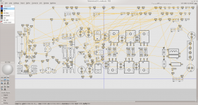
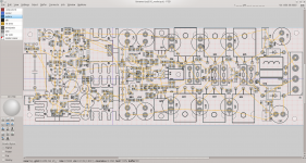
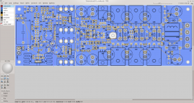
Spread them OP devices out. why is everybody packin' those pairs in so close ?
OS
- Home
- Amplifiers
- Solid State
- 2stageEF high performance class AB power amp / 200W8R / 400W4R