I always have to redraw the LTspice asc ...
This is what I wanted to avoid, of course.
I believed that PCB had a netlist import, not ASC, so I expected that could be used with LTSpice netlist output.
Hard to believe that no software exists that can take LTSpice output to PCB.
I will keep you informed if I find any.
Best wishes
David
When you actually use it (and abuse it)
I'm doing it now ...
Thermally , what I "shared" is golden .
Do it like I do it , and it will last - I'm really "pushin' it now.
I want mine to survive in a crackhouse.
OS
I'm doing it now ...
Thermally , what I "shared" is golden .
Do it like I do it , and it will last - I'm really "pushin' it now.
I want mine to survive in a crackhouse.
OS
This is what I wanted to avoid, of course.
I believed that PCB had a netlist import, not ASC, so I expected that could be used with LTSpice netlist output.
Hard to believe that no software exists that can take LTSpice output to PCB.
I will keep you informed if I find any.
Best wishes
David
One could write a program to convert ltspice generated netlist files which pcb/geda could read. As all files are in ascii format there should be no showstopper.
One big problem is: you need a valid "footprint" entry so pcb can select the correct part outline. Is there a comfortable attribute editor in ltspice available where you can add/change extra attribute name/value pairs per device?
Using e.g. LTSpice/WireList for export: The exported generic names like "resistor", "pnp" or "zener" are useless to get the correct package outline.
BR, Toni
...you need a valid "footprint" entry so pcb can select the correct part outline. Is there a comfortable attribute editor in ltspice available...
Andy Connors, an expert ex-DIY member looked at this and had a site with some information on how he did it.
I didn't really absorb the details, will have to recheck it.
EasyEDA looks like it has promise.
Best wishes
David
Andy Connors, an expert ex-DIY member looked at this and had a site with some information on how he did it.
I didn't really absorb the details, will have to recheck it.
EasyEDA looks like it has promise.
Best wishes
David
Thx! Will look for EasyEDA ...
Have had a deeper look into the source code of pcb/geda. It should be not big problem to convert a ltspice netlist file into a pcb/geda specific data.
pcb's import program gnetlist can be overridden, so it would be very easy to implement a ltspice importer ...
We only need some exact footprint data per device or we add an extra import list where we can save the footprint information like e.g. "C3 = WIMA_7x5_rm5". Could be a simple spreadsheet file exported as CSV. Here you can add also BOM information.
Are you able to run pcb/geda and some perl programs on your preferred platform?
Br, Toni
Spread them OP devices out. why is everybody packin' those pairs in so close ?
OS
IMHO if the maximum heat dissipation is distributed over so many devices they need not to be spreaded. See above SOA simulation. Every device is SOA limited to a max. power dissipation of < 96W. As this is only a half cycle each power device has a maximum mean power dissipation of about < 48W.
If the short circuit lasts long enough the overheat protection will shutdown the amplifier if heatsink reaches e.g. > 55 degree C.
The "big brother" SA2014 which uses 16 power devices and a similar transistor mounting distance has no thermal problem running continuous (!) 400W@4R sinus
BR, Toni
...Are you able to run pcb...
Can't run much at the moment.
AVG crashed my machine, possibly because Dell has some proprietary drivers. This also made it impossible to use a standard Linux-ish kernel to recover.
Attempted to reinstall Windows but this went half way before it asked for the product key and then rejected the one I have, maybe a mix up with the disc.
So my main machine is unusable, time for a new one anyway but I will need a few days.
In the meantime here is a link to Andy's work on LTSpice to PCB footprint conversion. Using LTspice With FreePCB
Looks to be pretty useful.
Best wishes
David
Hi David,
thats not really good news. Install a linux machine and run LTspice within "wine" - is faster as running native under Windows (no joke!).
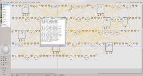
Regarding LTSpice2PCB: I have good news for you! Today I have written a perl program which is able to read a LTspice "asc" and LTspice "WireList netlist" file and generates a BOM (first step) and a pcb/geda readable part/netlist file (2nd step - needs BOM file with added footprint data).
Generated BOM with added footprint and pin renumbering data looks currently like:
D13 zener diode_zener_rm2.54 <remap> Z15
L1 ind diode_zener_rm2.54 <remap> 0.8µ
L2 ind diode_zener_rm2.54 <remap> 1.4mH
L3 ind diode_zener_rm2.54 <remap> 10mH
L4 ind diode_zener_rm2.54 <remap> 0.33mH
M1 nmos TO247AC gds IRFP240Ckst
M2 pmos TO247AC gds IRFP9240Ckst
M3 nmos TO247AC gds IRFP240Ckst
M4 pmos TO247AC gds IRFP9240Ckst
M5 nmos TO247AC gds IRFP240Ckst
M6 pmos TO247AC gds IRFP9240Ckst
Q1 pnp TO92-KL cbe BC560C
Q2 pnp TO92-KL cbe BC560C
Q3 npn TO126_FLAT ecb KSC3503
Fields are delimited by "TAB". Field number 1,2,5 are provided by converter program, field 3 and 4 is "footprint" and "pin reordering" (e.g. ebc, cbe or 3,1,2). A newer version could contain footprints as comments in the asc file (e.g.: "; footprint Q3=TO126_FLAT").L1 ind diode_zener_rm2.54 <remap> 0.8µ
L2 ind diode_zener_rm2.54 <remap> 1.4mH
L3 ind diode_zener_rm2.54 <remap> 10mH
L4 ind diode_zener_rm2.54 <remap> 0.33mH
M1 nmos TO247AC gds IRFP240Ckst
M2 pmos TO247AC gds IRFP9240Ckst
M3 nmos TO247AC gds IRFP240Ckst
M4 pmos TO247AC gds IRFP9240Ckst
M5 nmos TO247AC gds IRFP240Ckst
M6 pmos TO247AC gds IRFP9240Ckst
Q1 pnp TO92-KL cbe BC560C
Q2 pnp TO92-KL cbe BC560C
Q3 npn TO126_FLAT ecb KSC3503
Pin number conversion is also done automatically for npn, pnp, njf, pjf,nmos,pmos,polcap,diode ...
Simple variables will be expanded too (e.g.: {Rbias} will be replaced by the latest active .param statement).
LTspice2PCB forward annotation is currently untested but may work too.
Attached a successful imported asc file from the current 50W MOSFET amplifier (footprints are not always the correct one - was only for 1st test)
If there is some real interest I will provide this as an opensource toolkit.
BR, Toni
Attachments
...Today I have written a perl program which is able to read a LTspice "asc" and LTspice "WireList netlist" file...
If there is some real interest I will provide this as an opensource toolkit.
That's very impressive.
I have no perl expertise but I will learn just to have a look.
There should be real interest, if not then it only shows a lack of people with the skills to appreciate such work.
Best wishes
David
We grovel at your feet oh Guru Toni 😱Regarding LTSpice2PCB: I have good news for you! Today I have written a perl program which is able to read a LTspice "asc" and LTspice "WireList netlist" file and generates a BOM (first step) and a pcb/geda readable part/netlist file (2nd step - needs BOM file with added footprint data).
.....
Hi Toni,
How is going with the 200 W mosfet CFA?
Damir
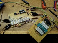
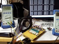
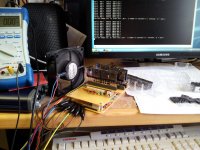
Some parts are missing and MOSFETs have to be matched for the 200W CFA and also for my new 50W MOSFET VFA.
Attached some pictures from my "mass transistor matcher" prototype in action.
... more in ~ 1 or 2 weeks ... 😉
BR, Toni
Attachments
Is this a current limiter or have you implemented some kind of load resistance detector?..............The simple current limiter will start limiting at about 1.5R load.............
A simple current limiter will detect a current and if excessive will trigger some reaction.
So, does your "simple current limiter" trigger at some actual current?
At what current will it start to affect operation and at what current will it have entered full limiting?
Last edited:
We grovel at your feet oh Guru Toni 😱
Thanks! 🙂
BR, Toni
Is this a current limiter or have you implemented some kind of load resistance detector?
A simple current limiter will detect a current and if excessive will trigger some reaction.
So, does your "simple current limiter" trigger at some actual current?
At what current will it start to affect operation and at what current will it have entered full limiting?
"SA2014 / 200W@8R" has only a simple current limiter which begins with current limiting if the load resistance goes below 1,5R.
BR, Toni
woww astx where you get all these stuff
... over so many years (started with DIY electronics at about 1977) 😉
BR, Toni
A current limiter is not an impedance/resistance measuring circuit."SA2014 / 200W@8R" has only a simple current limiter which begins with current limiting if the load resistance goes below 1,5R.
BR, Toni
Some parts are missing and MOSFETs have to be matched for the 200W CFA and also for my new 50W MOSFET VFA.
Attached some pictures from my "mass transistor matcher" prototype in action.
... more in ~ 1 or 2 weeks ... 😉
BR, Toni
Hi Toni,
Could you explain/show how you do MOSFET matching? I am not sure what is best simple way to do that.
BR Damir
- Home
- Amplifiers
- Solid State
- 2stageEF high performance class AB power amp / 200W8R / 400W4R