Yes, the position of the probe is correct, but it does not give the loop gain of the inner loop, if the outer loop is active.
Hi Harry
Yes, I should have been clearer, my only excuse is that it was late here (Australian Time).
I usually make a point to use Bode's term "Return Ratio" to make a distinction between the gain at the active devices and the gain in a loop.
The probe correctly shows the Return Ratio and this is what is critical.
More later.
Best wishes
David
and on that subject, notice the phase behaviour?
Phase leads as the gain drops.
David, I think Harry has identified the cause of the NMP behaviour.To observe the inner loop loop gain, you need to disable the global loop at AC (global loop DC feedback still required in order to bias the amplifier properly). This can be done by shorting the +ve and -ve inputs to ground via 1 kF capacitors.
The 'main loop' is the '2nd path' that is the necessary but insufficient condition for NMP. Obvious with hindsight 😱
It also demonstrates another 'necessary' condition which is easily shown in room responses but for which I don't have a clear theoretical handle. This is that the 'slower or later' path have larger magnitude than the 'direct' path.
______________________________
This beach bum grovels at Toni's feet for this most useful tool. 😱I should have said before - thanks to astx for bringing the “table” keyword/syntax to my attention - this looks like it could be very handy!
If I might clarify some of the documentation ...
.step param cnt list 1 2 3 4
.param pra table(cnt, 1, -1, 2, 1, 3, 0, 4, 0)
.param prb table(cnt, 1, 0, 2, 0, 3, -1, 4, 1)
sets up the sim to display up to 4 different changes to a parameter which are defined as
.step param Cm list 2p 4p 6p 8p
Then if the permanent additions to C:\Program Files\LTspice4\plot.defs have been made ...
you can simply 'Add trace' TianA1() etc to the pane of your choice
The 'main loop' is the '2nd path' that is the necessary but insufficient condition for NMP.
Yes, I think this is a useful way to consider it.
It also demonstrates another 'necessary' condition which is easily shown in room responses but for which I don't have a clear theoretical handle. This is that the 'slower or later' path have ...
Yes to this too, I have also seen this and seen some discussion in a paper on room equalization. Their position was the same as yours, no clear theory but easily seen.
...clarify some of the documentation ...
.step param cnt list 1 2 3 4
.param pra table(cnt, 1, -1, 2, 1, 3, 0, 4, 0)
.param prb table(cnt, 1, 0, 2, 0, 3, -1, 4, 1)
sets up the sim to display up to 4 different changes to a parameter which are defined as
.step param Cm list 2p 4p 6p 8p
Sorry but I don't think this clarifies it.
Parameter cnt runs from 1 to 4 to set up 2 different runs for each of the 2 probes.
The parameter Cm only has 4 different values by co-incidence, could be any number if you add extra Tian definitions.
Best wishes
David
David's answer is the correct one.
Define 2 Tian probes "run":
TianA2 represents result of Cm=4p
TianA3 represents result of Cm=6p
TianA4 represents result of Cm=8p
TianB1 represents result of Cm=2p
TianB2 represents result of Cm=4p
TianB3 represents result of Cm=6p
TianB4 represents result of Cm=8p
If you need e.g. one more step of Parameter Cm you have to add 2 more "TianAn()" and "TianBn()" functions to your local "plot.defs" file:
BR, Toni
Define 2 Tian probes "run":
.step param cnt list 1 2 3 4
Enable probe A at cnt "1" and "2":
.param pra table(cnt, 1, -1, 2, 1, 3, 0, 4, 0)
Enable probe B at cnt "3" and "4":
.param prb table(cnt, 1, 0, 2, 0, 3, -1, 4, 1)
Step parameter "Cm" with up to 4 values:
.step param Cm list 2p 4p 6p 8p
TianA1 represents result of Cm=2p
TianA2 represents result of Cm=4p
TianA3 represents result of Cm=6p
TianA4 represents result of Cm=8p
TianB1 represents result of Cm=2p
TianB2 represents result of Cm=4p
TianB3 represents result of Cm=6p
TianB4 represents result of Cm=8p
If you need e.g. one more step of Parameter Cm you have to add 2 more "TianAn()" and "TianBn()" functions to your local "plot.defs" file:
.func TianA5() {-1/(1-1/(2*(I(Vi)@17 *V(x)@18 -V(x)@17 *I(Vi)@18 )+V(x)@17 +I(Vi)@18 ))}
.func TianB5() {-1/(1-1/(2*(I(Vj)@19 *V👍@20 -V👍@19 *I(Vj)@20 )+V👍@19 +I(Vj)@20 ))}
It would be easy to add another (3rd) Tian Probe "C":.func TianB5() {-1/(1-1/(2*(I(Vj)@19 *V👍@20 -V👍@19 *I(Vj)@20 )+V👍@19 +I(Vj)@20 ))}
.step param cnt list 1 2 3 4 5 6
.param pra table(cnt, 1, -1, 2, 1, 3, 0, 4, 0, 5, 0, 6, 0)
.param prb table(cnt, 1, 0, 2, 0, 3, -1, 4, 1, 5, 0, 6, 0)
.param prc table(cnt, 1, 0, 2, 0, 3, 0, 4, 0, 5, -1, 6, 1)
"plot.defs":.param pra table(cnt, 1, -1, 2, 1, 3, 0, 4, 0, 5, 0, 6, 0)
.param prb table(cnt, 1, 0, 2, 0, 3, -1, 4, 1, 5, 0, 6, 0)
.param prc table(cnt, 1, 0, 2, 0, 3, 0, 4, 0, 5, -1, 6, 1)
.func TianA1() {-1/(1-1/(2*(I(Vi)@1 *V(x)@2 -V(x)@1 *I(Vi)@2 )+V(x)@1 +I(Vi)@2 ))}
.func TianB1() {-1/(1-1/(2*(I(Vj)@3 *V👍@4 -V👍@3 *I(Vj)@4 )+V👍@3 +I(Vj)@4 ))}
.func TianC1() {-1/(1-1/(2*(I(Vk)@5 *V(z)@6 -V(z)@5 *I(Vk)@6 )+V(z)@5 +I(Vk)@6 ))}
.func TianA2() {-1/(1-1/(2*(I(Vi)@7 *V(x)@8 -V(x)@7 *I(Vi)@8 )+V(x)@7 +I(Vi)@8 ))}
.func TianB2() {-1/(1-1/(2*(I(Vj)@9 *V👍@10 -V👍@9 *I(Vj)@10 )+V👍@9 +I(Vj)@10 ))}
.func TianC2() {-1/(1-1/(2*(I(Vk)@11 *V(z)@12 -V(z)@11 *I(Vk)@12 )+V(z)@11 +I(Vk)@12 ))}
a.s.o.
Unfortunately the "@" (=selects a specific array element of the result data) does not accept variables, so we need so much copies of the "Tian" function..func TianB1() {-1/(1-1/(2*(I(Vj)@3 *V👍@4 -V👍@3 *I(Vj)@4 )+V👍@3 +I(Vj)@4 ))}
.func TianC1() {-1/(1-1/(2*(I(Vk)@5 *V(z)@6 -V(z)@5 *I(Vk)@6 )+V(z)@5 +I(Vk)@6 ))}
.func TianA2() {-1/(1-1/(2*(I(Vi)@7 *V(x)@8 -V(x)@7 *I(Vi)@8 )+V(x)@7 +I(Vi)@8 ))}
.func TianB2() {-1/(1-1/(2*(I(Vj)@9 *V👍@10 -V👍@9 *I(Vj)@10 )+V👍@9 +I(Vj)@10 ))}
.func TianC2() {-1/(1-1/(2*(I(Vk)@11 *V(z)@12 -V(z)@11 *I(Vk)@12 )+V(z)@11 +I(Vk)@12 ))}
a.s.o.
BR, Toni
Last edited:
...
I should have said before - thanks to astx for bringing the “table” keyword/syntax to my attention - this looks like it could be very handy!
You are welcome!
Thanks for showing us how we can set specific values for a specific Tian probe run!
BR, Toni
could one of you please explain how to "read" the gain and phase plots in post1240.
I think I understand the upper set.
Green goes too steep as it crosses the 0dB and this shows as phase margin approaching 0degrees @ ~ 2MHz. Whereas the lower curves are less steep at 0dB (in the range 2MHz to 3MHz) and it looks like phase margin ~80degrees at 2.5Mhz, if we choose the correct colour of curve.
Is my interpretation correct?
Can it be restated, to be clearer to others?
But the lower one is quite different. What do the curves mean?
Last edited:
Hi Guys,
You have successfully distracted me from my “real work”. I have tinkered more with my two-pole demo schematic (screenshots posted to Dadod’s thread) and would like to share it with you.
I have made it so that it does two Tian probes (global and inner loops), closed-loop (i.e. input to output) frequency response, and +ve and -ve supply rejection.
This revealed that compensating the inner loop at the base of the VAS/TIS harms the -ve rail PSR, but this can be fixed by dangling an identical RC network from the other collector of the current mirror.
Enjoy!
Harry.
Attachments
Last edited:
could one of you please explain how to "read" the gain and phase plots in post1240.
I think I understand the upper set.
Green goes too steep as it crosses the 0dB and this shows as phase margin approaching 0degrees @ ~ 2MHz. Whereas the lower curves are less steep at 0dB (in the range 2MHz to 3MHz) and it looks like phase margin ~80degrees at 2.5Mhz, if we choose the correct colour of curve.
Is my interpretation correct?
Can it be restated, to be clearer to others?
Yes, that is correct. Assuming the gain only crosses 0 dB once, the phase must be greater than -180 before the crossing point, otherwise the amplifier will be unstable.
If the amplifier is stable, it has:
- “gain margin”, which is -1*(the loop-gain gain in dB at the point where the phase is -180), and
- “phase margin” which is = (the loop-gain phase at the point where the gain is 0 dB) + 180.
In general, people get nervous if the gain margin is less than 6 dB and/or phase margin is less than 45 degrees.
But the lower one is quite different. What do the curves mean?
The lower one is a loop gain plot of the “inner” loop, which is the negative feedback loop consisting of Q17, Q11, C8. You can “read” it the same as any other loop-gain plot to assess stability of the loop, it just looks a bit unusual because the feedback element is a capacitor (=open circuit at DC), so there is no loop gain at DC.
Last edited:

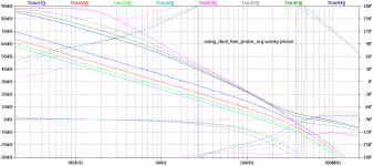
Non-Minimum Phase unicorn captured
The first pic is Toni's demo circuit. The 'inner Return Ratio' shows NMP behaviour with phase rising as amplitude drops.
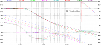
2nd pic shows .. if the feedback resistor R26 is made 27k, the path around the 'main loop' is now less than path via Cm and the behaviour is nicely Minimum Phase.
R26 =8k2 is interesting as the variation of Cm straddles the point where this changeover occurs.
No idea if this changeover has any significance in amp design/performance. The 'main loop' doesn't seem to show any strange behaviour as you cross this point. More work indicated.
But this may be the explanation for the various NMP unicorn sightings 😀
_______________
I've encountered this behaviour in the previous Millenium trying to sim Room Responses by FEA, BEA & other mumbo jumbo but never expected to see this so clearly in an amp. 🙂
_______________
Many thanks to Toni for the very clear explanation of his multiple Tians
Du.uuh! We can test the 2nd proposition by simply reducing the feedback around the main loop.The 'main loop' is the '2nd path' that is the necessary but insufficient condition for NMP. Obvious with hindsight 😱
It also demonstrates another 'necessary' condition which is easily shown in room responses but for which I don't have a clear theoretical handle. This is that the 'slower or later' path have larger magnitude than the 'direct' path.
The first pic is Toni's demo circuit. The 'inner Return Ratio' shows NMP behaviour with phase rising as amplitude drops.
2nd pic shows .. if the feedback resistor R26 is made 27k, the path around the 'main loop' is now less than path via Cm and the behaviour is nicely Minimum Phase.
R26 =8k2 is interesting as the variation of Cm straddles the point where this changeover occurs.
No idea if this changeover has any significance in amp design/performance. The 'main loop' doesn't seem to show any strange behaviour as you cross this point. More work indicated.
But this may be the explanation for the various NMP unicorn sightings 😀
_______________
I've encountered this behaviour in the previous Millenium trying to sim Room Responses by FEA, BEA & other mumbo jumbo but never expected to see this so clearly in an amp. 🙂
_______________
Many thanks to Toni for the very clear explanation of his multiple Tians
Attachments
Last edited:
Should point out that the unicorns here are at LF around 100kHz or so and will almost certainly be due to some "2 or more paths" issue. I don't think they are a problem.No idea if this changeover has any significance in amp design/performance. The 'main loop' doesn't seem to show any strange behaviour as you cross this point. More work indicated.
But this may be the explanation for the various NMP unicorn sightings 😀
But amps DO have NMP issues .. usually due to CE ceasing to transist but these will occur near or above ULGF .. see eg Baxandall on Self's "Baxandall Letters" page.
You need MP zeros at VHF to deal with these and they are as rare as unicorns.
______________________
To answer Harry about ensuring 'inner loops' are stable ...
When the amp overloads, the 'main loop' breaks. You need to ensure the 'inner loops' do something sensible in these circumstances.
This is often the cause of bursts of oscillation on overload, on parts of the waveform all dependent on the load, thermal & signal history .. that you see on many (all?) Golden Pinnae designs .. and this behaviour IS audible.
That should be easy to simulate, just overload in .tran simulation.
Don't forget to use different loads and also test this in real life tooThat should be easy to simulate, just overload in .tran simulation.
Gerber files ffor your MyDOA-V3.1 PCB's
Can you post the gerber files for your two test MyDOA-V3.1 PCB's? I would like to have some made up for my use. Take care.🙂
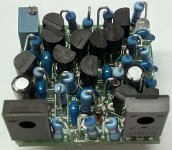
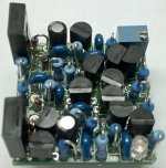
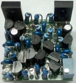
today the final MyDOA-V3.1 pcb's arrived.
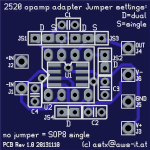
I have designed and ordered some 2520 adapter pcb's to be easily able to compare MyDOA with standard opamps.
BR, Toni
Can you post the gerber files for your two test MyDOA-V3.1 PCB's? I would like to have some made up for my use. Take care.🙂
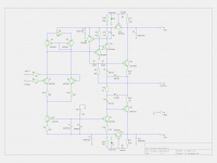
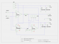
MyDOA v3.1 final
Attached MyDOA v3.1 schematic and gerber files.
NOTE: Only for private and non commercial usage!
Have fun!
BR, Toni
Attached MyDOA v3.1 schematic and gerber files.
NOTE: Only for private and non commercial usage!
Have fun!
BR, Toni
Attachments
-
my_doa_v3_class_ab_gerber.zip43.9 KB · Views: 529
-
my_doa_v3_class_ab_pcb.pdf155 KB · Views: 740
-
my_doa_v3_class_ab_schematic.pdf13.1 KB · Views: 1,059
-
 my_doa_v3_class_ab_schematic.png131.3 KB · Views: 3,623
 -
 my_doa_v3_class_ab_pcb.png108.2 KB · Views: 3,473
 -
 IMG_20140731_122458_1.jpg112.9 KB · Views: 1,059
 -
 IMG_20140731_122446_1.jpg125.7 KB · Views: 2,530
 -
 IMG_20140731_122433_1.jpg122.4 KB · Views: 2,674
 -
 IMG_20140731_122420_1.jpg132.5 KB · Views: 3,450
What about the Gergers for the 2528 Opamp adapter PCB?
What about the Gergers for the 2528 Opamp adapter PCB? I would like to
have these made as well.😉
What about the Gergers for the 2528 Opamp adapter PCB? I would like to
have these made as well.😉
2520 Adapter
For using single or dual opamps on a 2520 socket
BR, Toni
For using single or dual opamps on a 2520 socket
- dual DIL8 opamps like NE5532, LM4562
- single DIL8 opamps like NE5534
- single SOP8 opamps like LME49990
BR, Toni
Attachments

No idea if this ...has any significance... More work indicated.
I have responded to this in your thread http://www.diyaudio.com/forums/solid-state/235188-tpc-vs-tmc-vs-pure-cherry-9.html#post4253118
so as not to take over Toni's thread.
Best wishes
David
What PCB Vendor did you use for your PCB's
What PCB Vendor did you use to order you small and large PCB's?
I'm looking for specific suggestions so that I can order your PCB's. Take care
and great work.😀
What PCB Vendor did you use to order you small and large PCB's?
I'm looking for specific suggestions so that I can order your PCB's. Take care
and great work.😀
What PCB Vendor did you use to order you small and large PCB's?
I'm looking for specific suggestions so that I can order your PCB's. Take care
and great work.😀
I order all my PCBs online using this vendor: LeitOn
BR, Toni
- Home
- Amplifiers
- Solid State
- 2stageEF high performance class AB power amp / 200W8R / 400W4R