Toni, my notes are a bit disorganised but I got some oscillation coming out of overload in my sims like you show in #812 ONLY when I simmed the Ribbon cable.Stronger compensation wasn't done to prevent sticking at 20kHz. Only to find the reason for the oscillation bursts at overload using an 8R load. Removing the test load or increasing it to ~ 16R the oscillation bursts during 20kHz overload stop. Maybe my test setup is suboptimal (currently only 1/4 of the needed output power transistors are mounted, no ops pcb). The amplifier is stable using C1 = 47p which gives > 100V/µsec.
Simply need to find the reason for the overload bursts ... maybe someone can help here ...
But by that time, it was obvious that my sim and 'real life' were moving too far apart. 😡
If you do want to pursue the problem with sims, have a look at Q6 & 34 base currents. When the oscillations occur, these currents are huge. A small resistor in series with the bases helps damp things but I didn't investigate this fully.
On a completely different design, this overload oscillation effect happened on loads less than 2R. Again I didn't investigate properly but increasing the VAS current helped quite a lot.
This occurs in quite a lot of amps including many in Self's book.
Hope these hints are useful.
Last edited:
I can't find Q7 in post812, nor post815.
Which post shows Q7?
... Richard means Q34 which is in older asc files Q7 ...
...
On a completely different design, this overload oscillation effect happened on loads less than 2R. Again I didn't investigate properly but increasing the VAS current helped quite a lot.
...
Dear Richard,
increasing VAS current to 20mA helped a lot. Only a very short time we see a good damped sticking at 20kHz/8R load. See attached picture (measured be4 output coil). This small amount of sticking is also load dependent as you have described above (no load = no sticking).
To get the SOA right during overload on 2R we need 2 pieces KSA1381 (or switch back to 2SA1837🙁)
Simulated THD20k@200W@8R is now down to 1ppm. 🙂
The 2-piece-KSA1381-VAS needs to be verified in real life the next days...
BR, Toni
Attachments

...
The 2-piece-KSA1381-VAS needs to be verified in real life the next days...
it works like a charm...
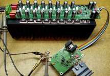
Attached picture shows the newer SA2013 v2 output stage pcb which was untested till yesterday.😉
Amp is stable using 2.2µF parallel with 8R load. Slew 80V/60V.
Quick test without DM: THD+N < 0.002@200W@8R (bw 80k) including VAS clamp diode. Sticking at 20kHz@8R overload bettered dramatically. Can't see any oscillations.
Attachments
The effect of current mirror degeneration on slew rate
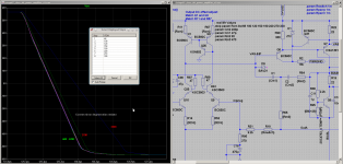
... today found the reason why the slew rate symmetry was not very good.
A too heavy degeneration of the ltp current mirror kills the slew rate.
To use 220R instead of 330R for the current mirror degeneration resistors seems to be a good compromise between slew rate symmetry and overall noise figure. 😉
Br, Toni
Attachments
SA2013 V3 - final beta
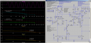
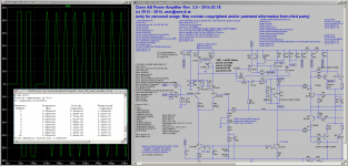
... attached the final beta of SA2013-V3 using TTC5200 and TTA1943 as ops transistors:
BR, Toni
... attached the final beta of SA2013-V3 using TTC5200 and TTA1943 as ops transistors:
- Slew rate symmetric > 80V
- no sticking at 20kHz@8R overload
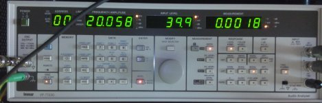
- THD+N@20k@200W@8R 0.0018% (bw 80kHz) - using DM the distortion reading is 0.0012%
- THD+N@10k@100W@8R 0.0009% (bw 80kHz, D.Self would call this an "ultra low distortion Amplifier" - "anything below 0.001%@10kHz")
- THD+N@1k@100W@8R 0.00044% (bw 80kHz)
BR, Toni
Attachments

That makes sense for a rather different reason.... today found the reason why the slew rate symmetry was not very good.
A too heavy degeneration of the ltp current mirror kills the slew rate.
To use 220R instead of 330R for the current mirror degeneration resistors seems to be a good compromise between slew rate symmetry and overall noise figure. 😉
Br, Toni
220r @ 2.5mA results in a Vdrop of 550mV
330r @ 2.5mA results in a Vdrop of 825mV.
The 330r causes much more than a sometimes recommended 600mV across the Current Mirror degeneration resistor.
What happens to changes in slew rate, if the tail current were 3mA instead of 5mA? Does that ~600mVdrop still give a useful guide value?
Why are C42 and C35 different?
For what conditions does the protection transistor Q37 start to turn on?
For what conditions does the protection transistor Q37 start to turn on?
Why are C42 and C35 different?
For what conditions does the protection transistor Q37 start to turn on?
Congratulations! You won the price to find the schematic error! 😉
C42, C35: 330p
Q37 is to SOA protect the VAS bjt's during heavy overload.
Attached the corrected asc file.
Attachments
That makes sense for a rather different reason.
220r @ 2.5mA results in a Vdrop of 550mV
330r @ 2.5mA results in a Vdrop of 825mV.
The 330r causes much more than a sometimes recommended 600mV across the Current Mirror degeneration resistor.
What happens to changes in slew rate, if the tail current were 3mA instead of 5mA? Does that ~600mVdrop still give a useful guide value?
Can't find the recommendation for 600mV. Maybe you can provide a link?
D.Self recommends at least 30 - 60 mV voltage drop at current mirror degeneration resistors (APAD6 / p132) ...
Br, Toni
New instrument for my measurement "park"
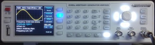
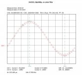
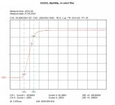
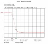
... not much news but more measurements using my brand new arbitrary generator. Have generated a special test curve based on an 1k sinus with overlay of an small signal 40k square wave. During test the output base frequency was set to 5kHz sinus which results in a 200kHz square wave small signal overlay.
Pictures
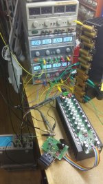
Parts of the zobel filter have been removed - only the 0.8µH output coil was present.
Would you consider this amplifier to be stable?
BR, Toni
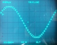
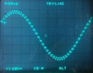
... not much news but more measurements using my brand new arbitrary generator. Have generated a special test curve based on an 1k sinus with overlay of an small signal 40k square wave. During test the output base frequency was set to 5kHz sinus which results in a 200kHz square wave small signal overlay.
Pictures
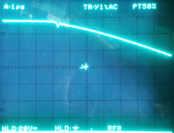
- Arbitrary function generator using own curve. 5kHz sin./200kHz sq.
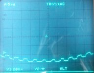
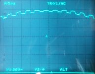
- 110Vpk output @ 8R near clipping
- 118Vpk clipping @ 8R (amplifier supply voltage ~ 122V)
- clipping details near positive supply voltage
- clipping details near negative supply voltage
- test setup
Parts of the zobel filter have been removed - only the 0.8µH output coil was present.
Would you consider this amplifier to be stable?
BR, Toni
Attachments
-
 my_new_arbitrary_generator.jpg56.3 KB · Views: 907
 -
1ksin_40ksq_10.zip48.2 KB · Views: 219
-
 test_setup_8r_load.jpg110 KB · Views: 444
 -
 sa2013_5ksin_200ksq_overload_3.jpg48.1 KB · Views: 877
 -
 sa2013_5ksin_200ksq_overload_2.jpg41.1 KB · Views: 881
 -
 sa2013_5ksin_200ksq_overload_1.jpg47 KB · Views: 895
 -
 sa2013_5ksin_200ksq_110Vpk_1.jpg39.6 KB · Views: 903
That looks good to me. I would do the same test for 1n-47n capacitor loads to see if it oscillates, and try to adjust the zobel if so.
Can't find the recommendation for 600mV. Maybe you can provide a link?
D.Self recommends at least 30 - 60 mV voltage drop at current mirror degeneration resistors (APAD6 / p132) ...
Self's recommendation in 5th edition is badly sub optimal, as discussed by Samuel here
I expected the 6th edition would be fixed because I pointed out Samuel's work to Self when he asked for comments.
The primary reference is Bilotti but he plots it as a function of the emitter resistor value.
Better to factor out the current mirror operational current and express it in mV.
600mV is OK. A little less noise if it is even more.
Unlike the emitter resistors in the OPS there is no practical "optimum" that corresponds to a null.
So the value is not critical, but after about 2V the reduction in noise is practically undetectable .
Best wishes
David
Like the new equipment😉 Seen this simulated so it is nice to compare with reality.
How many bits precision in the arbitrary function?
Last edited:
Dear Dave,
thanks for informing us!
Thx! Like it too.😉
From HMF2525 datasheet:
BR, Toni
thanks for informing us!
...
Like the new equipment😉 Seen this simulated so it is nice to compare with reality.
How many bits precision in the arbitrary function?
Thx! Like it too.😉
From HMF2525 datasheet:
- Amplitude resolution 14 bits
- Total harmonic distortion is < 70 dBc up to 100kHz
- Total harmonic distortion is < 55 dBc from 100kHz to 10MHz
- rise/fall time < 8ns typ.
- overshoot < 3%
BR, Toni
Measurement day ...
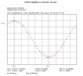
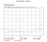
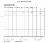
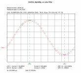
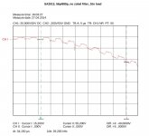
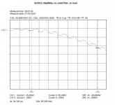
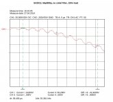
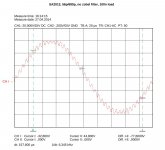
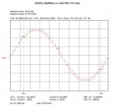
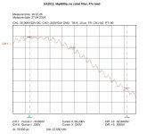
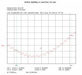
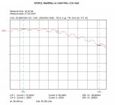
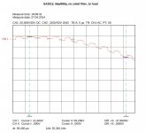
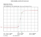
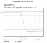
Some more detail measurements using 5kHz sinus with 200kHz small signal square wave overlay.
Some more detail measurements using 5kHz sinus with 200kHz small signal square wave overlay.
Attachments
-
 hameg_20140427160248.jpg90.6 KB · Views: 206
 -
 hameg_20140427160039.jpg94.2 KB · Views: 207
 -
 hameg_20140427155812.jpg89.2 KB · Views: 224
 -
 hameg_20140427155730.jpg89.5 KB · Views: 196
 -
 hameg_20140427155542.jpg93.9 KB · Views: 227
 -
 hameg_20140427155457.jpg93.9 KB · Views: 258
 -
 hameg_20140427155207.jpg89.3 KB · Views: 247
 -
 hameg_20140427155030.jpg89.3 KB · Views: 367
 -
 hameg_20140427160354.jpg90.6 KB · Views: 193
 -
 hameg_20140427160759.jpg89.8 KB · Views: 202
Measurement day (part 2)
... next picture series / part 2 ...
... next picture series / part 2 ...
Attachments
-
 hameg_20140427161529.jpg90.6 KB · Views: 185
 -
 hameg_20140427161453.jpg95.3 KB · Views: 186
 -
 hameg_20140427161311.jpg95.9 KB · Views: 182
 -
 hameg_20140427161241.jpg93.5 KB · Views: 172
 -
 hameg_20140427161214.jpg93.5 KB · Views: 167
 -
 hameg_20140427161124.jpg90.3 KB · Views: 181
 -
 hameg_20140427161032.jpg90.5 KB · Views: 166
 -
 hameg_20140427160844.jpg90.1 KB · Views: 190
 -
 hameg_20140427160815.jpg90.4 KB · Views: 200
Last edited:
Measurement day (part 3)
... last part.
TMC: 56p / 680p / 470R
Some THD values measured with VP7723D (without DM) / 80kHz bandwidth:
THD+N @ 100W @ 8R:
... last part.
TMC: 56p / 680p / 470R
Some THD values measured with VP7723D (without DM) / 80kHz bandwidth:
THD+N @ 100W @ 8R:
1kHz / 0.0004%
10kHz / 0.0008%
20kHz / 0.0009%
40kHz / 0.0018%
THD+N @ 200W @ 8R:10kHz / 0.0008%
20kHz / 0.0009%
40kHz / 0.0018%
1kHz / 0.0007%
10kHz / 0.0015%
20kHz / 0.0017%
40kHz / 0.0026%
SR: > 80V / µs10kHz / 0.0015%
20kHz / 0.0017%
40kHz / 0.0026%
Attachments
Last edited:
Why is the rise time of the sq wave faster on the leading edge during the rising sine wave (+) side and opposite on the down ward slope of the sine wave? Then it is slower on the leading edge during the falling of the sine wave (going neg - towards zero)?
Some of the square waves indicates maybe some slew limiting going on.... ? Can you test for the amps slew rate limites under loads??
THx-RNMarsh
Some of the square waves indicates maybe some slew limiting going on.... ? Can you test for the amps slew rate limites under loads??
THx-RNMarsh
Last edited:
- Home
- Amplifiers
- Solid State
- 2stageEF high performance class AB power amp / 200W8R / 400W4R