Understood. And what about the transient response? I think, that it's more important, than the THD.
Sajti
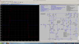
See attached sim. It looks pretty good. Overshoot due to TPC compensation is normal. No ringing!
Slew rate better 45V/µs.
Attachments
Last edited:
Using 2N5401 for Q1 and Q2 is a mistake. At low Vce these transistors perform badly.
The BC5x0, BC3x7, and 2SA1015 are known to have excellent okay quasi-sat behavior. There are virtually no transistors with Vcemax>50V that have good quasisat behavior.
Because SPICE does not model quasi-saturation, this problem will not show up in your simulations.
If Spice does not model quasi-saturation then how do you identify a transistor that works well in that area?
You use Vce(sat) to predict performance or have you done tests to select your preferred transistors?
In your setup matching the CM transistors isn't going to do anything if the CM degeneration isn't also matched.
I was always baffled by Self's insistence that CM avoided the reliance on resistor tolerances, and then to degenerate them with resistors!
I am tempted to use better than 1% resistors. The next readily available precision I have found to be 0.1% which seems overkill but is not too expensive anyway. Seem reasonable?
I go by Slone's advice to degenerate by 50mV. 50mV / 2.2mA =~ 22R. Degeneration is specified as voltage drop because Gm is proportional to Iq and so is the degeneration voltage drop. This way degeneration can be described conveniently independent of Iq.
Yes, it is smart to specify degeneration by potential difference.
Except that for minimum noise you want at least 260mV and there is asymptotic improvement up to about 2600mV!
In contrast noise will be much reduced in the LTP which is good, one shouldnt use low degeneration as Self or Slone suggest. Larger degeneration will lower the gain a little but... Noise can be lowered by as much as 15db.
Wish you had posted this when I asked a while back.
Took me some time to realize Self was not to be trusted on this!
At least it was educational to work it out for myself😉
Best wishes
David
Last edited:
Hi Dave. In my signature you'll see a link to my Kmultipliers. Any difference in quasi-sat behavior is seen on the PSRR of these things, which I measured in real life. BC3x7-40 have been the best by far, with the BC5xxC as runner-up. The surprising thing is that these transistors see a low base impedance, so the PSRR difference must be a result of Vbe itself changing due to quasi-saturation.
Vce(sat) may predict quasi-sat performance to some extent. However, quasi-sat is the transition between Vaf error and Vce(sat) error, so as well as having low quasi-sat, the ideal transistor must have reasonable Vaf. Joachim Gerhard posted several useful quasi-sat charts in the Mpp thread.
EDIT: link to measurements here:
http://www.diyaudio.com/forums/analogue-source/154210-mpp-167.html
EDIT: link to measurements here:
I plan to use an EF assisted CM anyway so I don't think I have a problem, just curious.
However the linked post doesn't seem relevant?
Best wishes
David
Here is the specific post:
http://www.diyaudio.com/forums/analogue-source/154210-mpp-167.html#post3353729
After this point there are more saturation-region curves.
It sounds like you're saying an EF assisted CM will fix the problems with quasi-saturation. Neither a this nor a buffered CE TIS will fix what is caused by quasi-saturation in the CM. This is because in the quasi-sat region collector impedance drops down to less than 1k. This is a 500R resistor effectively shunting the input of your VAS to the rail. Like I said, quasi-sat causes problems whether or not you have low impedance base drive, as in my Kmultipliers.
Static and dynamic CM imbalance are also possible problems with quasi-saturation but they are in addition to the above issue.
Your mileage will of course vary. It is as easy to make a good CM as a bad one if you aren't aware that quasi-sat can make the difference. Ultimately, you can measure the collector impedance at the Vce you plan to run the CM at, or you can derive it approximately from Joachim's charts or the datasheet charts if they are present. You could also take advantage of my anecdotal experience and use my recommendations.
...
It sounds like you're saying an EF assisted CM will fix the problems with quasi-saturation. Neither a this nor a buffered CE TIS will fix what is caused by quasi-saturation in the CM...
The EF helper transistor on the CM adds .6 Volts to Vce, so doesn't that take the CM out of quasi-saturation? Coupled with an EF assisted VAS/TIS to equalize the CM Vce?
I am new to this topic so perhaps I misinterpret Joachim's data?
Keen to learn
David
You're quite right, Dave, in some cases. In some popular japanese transistors, quasi-sat reaches out to as far as 2V. After this point, it transitions to normal Early behavior. Within the quasi-sat region collector impedance is a relatively constant 500R or so. You may not have any problems depending on the topology. I suggest you don't rule out this problem at the moment and do some tests with your prototype. A high CM output impedance is necessary to take advantage of the high input impedance of a buffered CE TIS.
Some measurements with R17=150R
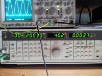
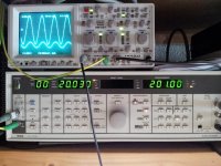
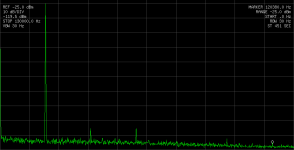
Yesterday made some measurements with R17=150R.
Most of the H2/H3 is produced from the analyzer oscillator output itself.
Load 8R, 200W, 20kHz.
Yesterday made some measurements with R17=150R.
Most of the H2/H3 is produced from the analyzer oscillator output itself.
Load 8R, 200W, 20kHz.
Attachments
If Spice does not model quasi-saturation then how do you identify a transistor that works well in that area?
You use Vce(sat) to predict performance or have you done tests to select your preferred transistors?
I was always baffled by Self's insistence that CM avoided the reliance on resistor tolerances, and then to degenerate them with resistors!
I am tempted to use better than 1% resistors. The next readily available precision I have found to be 0.1% which seems overkill but is not too expensive anyway. Seem reasonable?
Yes, it is smart to specify degeneration by potential difference.
Except that for minimum noise you want at least 260mV and there is asymptotic improvement up to about 2600mV!
Wish you had posted this when I asked a while back.
Took me some time to realize Self was not to be trusted on this!
At least it was educational to work it out for myself😉
Best wishes
David
Dear David and Keantoken,
thank your for this interesting discussion about current mirrors. What me confuses now:
- keantoken: 22R@2.2mA would be good (=50mV degeneration)
- David: 120R@2.2mA (> 260mV degeneration) minimum would be needed for better noise figure
Can we say: 50mV degenerated CM is of more precision and > 260mV is for better noise figure?
BR, Toni
Dear David and Keantoken,
thank your for this interesting discussion about current mirrors. What me confuses now:
- keantoken: 22R@2.2mA would be good (=50mV degeneration)
Is there a formula for DIYers for customizing CM features?
- David: 120R@2.2mA (> 260mV degeneration) minimum would be needed for better noise figure
Can we say: 50mV degenerated CM is of more precision and > 260mV is for better noise figure?
BR, Toni
No, that would be incorrect.
The higher voltage drop would mean more precision (depending on parts matching), lower noise, better CM stability and higher output impedance.
The only bad feature is loss of gain but the effect this has on THD is so small its a no brainer.
A 260mV drop is still small but it will already make a very usefull drop in noise.
... more precision ..., lower noise, better CM stability and higher output impedance.
The only bad feature is loss of gain but the effect this has on THD is so small its a no brainer.
Hi Toni
As to formula, I would use at least 260 mV and not exceed 2600mV = 2.6V.
Beyond 2.6V there is no real noise improvement and headroom lose may start to hurt.
I have bi-amp directly connected to compression drivers so noise is my major concern.
More precision than ever needed is easy with precision resistors.
I have not yet simulated or tested "manso"s other points.
The loss of gain could probably be offset with lower emitter resistors for the LTP.
Best wishes
David.
How would the CM gain with 260mV drop on the degen resistors compare to using no CM and just using resistor collector loads with a 600mV drop?
Distortion analysis for R17=150R
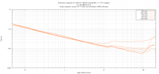
See attached distortion plot for SA2013 using R17=150R.
At very high power levels (100W - 200W) the THD values for 20Hz, 200Hz and 1kHz would be a little bit better if the used regulated laboratory power supplies wouldn't start activating the current limiter...
Can someone compare these results with other real life amplifiers out there to get a feeling in which category the 2stageEF may be playing?
BR, Toni
Attachments
CM degeneration
Dear David, Manso, Keantoken and AndrewT,
thanks for input. CM changes will be tested next days. First of all I will replace the 2N5401 by BC560C. The current mirror degen resistors will get a socket so different values can be tested.
Btw: replacing the CM by a simple resistor does not simulate well. About 680R is necessary to get acceptable offset values. Even on reducing the degeneration resistor of the LTP pair, the THD is very bad. No good idea to remove the CM...
BR, Toni
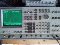
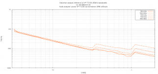
Audio Analyzer Reference Plot ...
attached a distortion plot of audio analyzer itself for comparison. The 2StageEF distortion plot is only a few ppm higher ...
BR, Toni
See attached distortion plot for SA2013 using R17=150R.
At very high power levels (100W - 200W) the THD values for 20Hz, 200Hz and 1kHz would be a little bit better if the used regulated laboratory power supplies wouldn't start activating the current limiter...
Can someone compare these results with other real life amplifiers out there to get a feeling in which category the 2stageEF may be playing?
BR, Toni
attached a distortion plot of audio analyzer itself for comparison. The 2StageEF distortion plot is only a few ppm higher ...
BR, Toni
Attachments
After changing the current mirror, what will greatly reduce the VAS distortion is to put R17 across the B-E of Q11, instead of including the degeneration. Then replace Q9 with a fast high-gain transistor. OStripper uses the KSA992. If the voltage were lower I'd use a BC560C.
The 22pF bridge cap on the TPC may not help stability and circumvents the improvement of TPC. I would suggest you try removing it.
The ratio of C8 and C10 could be better. For TPC you want C10 to be around 5 times C8. for less input stage loading you can reference R16 to Q11's emitter. R16 should not go to ground, else you are causing PSRR.
I get 390p, 82p and 3.9k as new values for C8, C10 and R16 respectively for the same corner frequency and miller capacitance after eliminating the bridge cap.
I think the above changes as well as the CM may greatly reduce THD, although it seems you'll only be able to see the effect in simulation.
Also astx, after making these changes if you eliminate the current mirror by using a resistor across the B-E of Q9, you will have the least reduction in performance. In this topology performance improves proportionally when you lower R17 until other mechanisms dominate. You may be surprised how well this works.
The ratio of C8 and C10 could be better. For TPC you want C10 to be around 5 times C8. for less input stage loading you can reference R16 to Q11's emitter. R16 should not go to ground, else you are causing PSRR.
This is not correct. To get the best PSRR, R16 should go to ground and the C8/C9 junction should go to Q2 emitter instead of collector. Note that this altered connection will probably require compensation to the minor loop. See section 3.4 and addendum of my paper on two-pole compensation.
- Home
- Amplifiers
- Solid State
- 2stageEF high performance class AB power amp / 200W8R / 400W4R