I've been meaning to make my way through this:
https://people.rit.edu/lffeee/SPICE_MOSFET_Model_Intro.pdf
Ooooh thanks! Looks pretty, pretty and pretty simple. Will immediately redesign all my mosfet models. 😎
SA2016: using lateral mosfets ECW20N20 ECW20P20
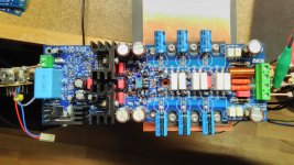
... attached some pictures showing the new test sample using double die MOSFETs ECW20N20 ECW20P20.
It is working as expected. 🙂 I only have matched the Exicons. All other transistors I have used from the same lot without further checking.
The calculated low value gate resistors of 150R/68R (see table some post ago) lead to the same oscillation problem as I have had testing the ECX10N20/EXC10P20 pairs. The OPS starts oscillating (~ 16Mhz) if total bias is over 700mA (about 230mA Bias per pair). A quick test using 330R/220R gate resistors stopped oscillations. Even with 3A total bias no more oscillations. The next days more test will follow.
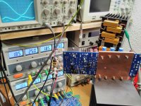
Test conditions: Power supply +/- 50V stabilized. Total Bias 450mA. Right picture shows 1kHz@120W@8R performance and distortion residual (Ch2).
THD:
... attached some pictures showing the new test sample using double die MOSFETs ECW20N20 ECW20P20.
It is working as expected. 🙂 I only have matched the Exicons. All other transistors I have used from the same lot without further checking.
The calculated low value gate resistors of 150R/68R (see table some post ago) lead to the same oscillation problem as I have had testing the ECX10N20/EXC10P20 pairs. The OPS starts oscillating (~ 16Mhz) if total bias is over 700mA (about 230mA Bias per pair). A quick test using 330R/220R gate resistors stopped oscillations. Even with 3A total bias no more oscillations. The next days more test will follow.
Test conditions: Power supply +/- 50V stabilized. Total Bias 450mA. Right picture shows 1kHz@120W@8R performance and distortion residual (Ch2).
THD:
- 1k@120W@8R: 0.0007 %
- 20k@120W@8R: 0.0037 %
- 104 dB full bw
- 114 dB 80k bw
- 121 dB A-w
Attachments
Last edited:
Ooooh thanks! Looks pretty, pretty and pretty simple...
It looks a useful introduction to IC MOSFET models.
Unfortunately, not much use for discrete power MOSFETs AFAIK.
I think the only real option in LTspice is the VDMOS model.
Luckily it seems excellent, improved to the point it is the best power MOS model of any Spice, also AFAIK.
Cordell, Keantoken and others had an educational discussion in DIYaudio.
I would use that as the primary resource.
Best wishes
David
Toni, nice work, as always, in fact so always that it almost seems redundant to say it.
I really want to see what you could do with the 500 W IXYs Fets.😉
Last edited:
That will take a bit to remember.OK - that was the pcb "SA2015 rev. 1.4 2016.06.17" - wrong named (name was reserved for the vertical mosfet "SA2015" amp) and with trace error but can be made working using a knife and is after-wards electrical identical with the corrected pcb "SA2016 rev 1.6.2 2016.08.07".
Many Alfet and Exicon circuit examples are showing 330R for N-channel and 220R for P-channel gate resistors for single die mosfets.
A double die chip has 2 times the Ciss and the questions is: will the mosfet be stable if we reduce the gate resistor to represent the same cut off frequency?
BR, Toni
I see I mistook rev. 1.4 as 2014, when what I have is identical to SA21016 rev 1.6.2 after the small surgery.
I still have single slope miller feedback (Cdom) and biased to three times 200mA (total 600mA) @ 50V for 62W dissipation per channel.
SA2016: using lateral mosfets ECW20N20 ECW20P20
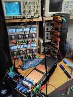
Test conditions: +/-62V regulated; RgateN 270R; RgateP 180R; overcurrent protection in situ
THD20k+N@200W@8R: 0.0052% 🙂
This measurement was taken with sagging rail voltages from power supply (~ +/-58V) just before power supply current limit:
THD20k+N@320W@4R: 0.008% 🙂🙂
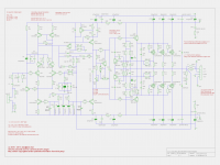
Attached the preliminary schematic!
BR, Toni
Note: Schematics are free to use only for non commercial DIY projects.
WARNING: the circuit is using and providing very high AC and DC voltages and is therefore very dangerous and can be lethal. I am not responsible for any costs, damage and/or injury using these schematics. Do not use this schematics if you do not have the necessary experience and knowledge.
Test conditions: +/-62V regulated; RgateN 270R; RgateP 180R; overcurrent protection in situ
THD20k+N@200W@8R: 0.0052% 🙂
This measurement was taken with sagging rail voltages from power supply (~ +/-58V) just before power supply current limit:
THD20k+N@320W@4R: 0.008% 🙂🙂
Attached the preliminary schematic!
BR, Toni
Note: Schematics are free to use only for non commercial DIY projects.
WARNING: the circuit is using and providing very high AC and DC voltages and is therefore very dangerous and can be lethal. I am not responsible for any costs, damage and/or injury using these schematics. Do not use this schematics if you do not have the necessary experience and knowledge.
Attachments
Last edited:
SA2016 using IXYS power MOSFETs
Thx! Just ordered some test samples of
The simulation works so far with some errors. I need at least a new bias generator because of the higher needed gate voltage to drive the power horses...
BR, Toni
...
Toni, nice work, as always, in fact so always that it almost seems redundant to say it.
I really want to see what you could do with the 500 W IXYs Fets.😉
Thx! Just ordered some test samples of
- IXTH80N20L (200V, 80A, 0.032Rdson)
- IXTH48P20P (200V, 48A, 0.085Rdson)
The simulation works so far with some errors. I need at least a new bias generator because of the higher needed gate voltage to drive the power horses...
BR, Toni
Attachments
Do you prefer standard miller compensation over the new TMC variants?...
I still have single slope miller feedback (Cdom) and biased to three times 200mA (total 600mA) @ 50V for 62W dissipation per channel.
What value are you using for your miller cap and RgateN and RgateP so I can verify it here in my lab?
AFAIK you are using the double die Exicons too?
BR, Toni
don't just multiply up the bias voltage. That multiplies the Tempco................. I need at least a new bias generator because of the higher needed gate voltage to drive the power horses..............
You need a very slightly higher Tempco, but with a much higher bias voltage.
Yes - e.g. with 2 red LEDs in series ... but first we need the test samples ...don't just multiply up the bias voltage. That multiplies the Tempco.
You need a very slightly higher Tempco, but with a much higher bias voltage.
I'm using double die Alfets. ALF16n20W & 16p20W
I think I used a 56pF for the Miller comp Cdom.
I have not tried the TMC, this would be the first I have done and I am not yet comfortable with what testing is required to prove it is sufficiently stable into all reasonable loads.
So far the IV protection is not populated.
Could you post a scope pic of what the triggering looks like when testing the protection limit?
two RED LEDs sounds like a lot. That comes to ~4VYes - e.g. with 2 red LEDs in series ... but first we need the test samples ...
Apply a multiplication of 1.7times to give a bias voltage of ~ 6.8V and a Tempco of 1.7times the change in sensor temperature.
Might be close, or not?
Have you tried gluing the sensor sot23 to the collector/source lead?
Upside down leaves the leadouts pointing away from the thick leadout ready to take three fine wires, or soldered to a tiny PCB 2mm square. I have done both and they work. MUCH better than the more remote sensors used nearly everywhere else.
...Just ordered some test samples of
IXTH80N20L (200V, 80A, 0.032Rdson)
IXTH48P20P (200V, 48A, 0.085Rdson)
That should be fun😉
...IXTH50P10.lib and IXTH88N30P.lib - for the above ordered mosfets I can't find usable models so I took some similar types...
Only Level 3 models, I expect you already know the distortion simulation will be useless, and I would not trust the stability as the output nears the rails.
But the capacitance looks reasonable for a basic simulation around quiescent operation point, I expect you already know that too😉
Best wishes
David
...
ALF16n20W & 16p20W
...
So far the IV protection is not populated.
Could you post a scope pic of what the triggering looks like when testing the protection limit?
Good to know that we can use the ALFET's too.
Don't know which type of scope picture you want to see here. Or is it allowed to upload a video showing the holy smoke? 😎
BR, Toni
...
Have you tried gluing the sensor sot23 to the collector/source lead?
...
No! Don't like mounting the bias temperature sensors using "long" cables ...
I can't see the benefit to do so. Using MOSFETs in general it is not really a problem if the bias increases a little bit due to short transient peaks.
BR, Toni
there is an AC test using a capacitor and squarewave to send pulses into the load.............................Don't know which type of scope picture you want to see here.............
The scope monitors the shape of the deformed square wave.
There is a shelf in the slope that indicates the current limiter set value.
I think ESP & Pass describe the test.
I have never tried it in case the limiter does not work and I blow up a good amplifier.
The benefit is faster tempco correction and more accurate holding of set bias power. Once set up the power dissipated is held pretty constant and thus temperature of the output stage can be set to hold nearly constant with changes in ambient temperature, or the output stage temperature can track the ambient temperature holding a near constant Tout-Ta differential.........................I can't see the benefit to do so..................
Or it can be slightly overcompensated to reduce the bias power when Ta rises.
This is not a problem with a high bias Lateral mosFET output stage where the devices are virtually self compensating and the distortion does not go wrong when under-biased.
Slightly different when going to Vertical mosFETs which need Tempco to ensure thermal run-away cannot happen.
And even more important with an optimally biased BJT output stage.
I'm using double die Alfets. ALF16n20W & 16p20W
I think I used a 56pF for the Miller comp Cdom.
...
Distortion figures of double die Exicons with simple Miller 56p and 330R/220R gate resistors, +/-50V supply:
- THD1k+N @100W@8R: 0.0006%
- THD20k+N @100W@8R: 0.0075%
The more I test the more it is clear we must use 330R and 220R as gate resistors. Settings those gate resistors to 330R/220R and a Miller cap as low as 10p the amp ist still stable.
Reducing the gate resistors below 270R/180R the amp starts oscillation (200mVpp around 15-16mHz) if I increase the total bias above 700mA.
Strange that we must use higher gate resistors using the double die Exicons ...
...
There is a shelf in the slope that indicates the current limiter set value.
I think ESP & Pass describe the test.
...
Do you mean this procedure described here: VI Limiters in Amplifiers
Have tried this using a 1.2mH air coil and 1R resistor. My lab power supply has too less power - the rails are sagging be4 the current protection starts to work ...
Are Latfets more forgiving than bjts?, so in other words, you do not need the hard IV limiter ckt, you can still sense the over current, as you do but use this to trigger a relay to open the connection to the speaker/load. I assume that you use a speaker relay as isolation for a DC over voltage condition.
I wonder also if you have tried any of Bob C's suggestion of zobels in the gate leads as well as the series R's? That way you might be able to lower the series R.
What are you measuring as a rise/fall time? On the OPC wireamp, I measured in the order of 620/650ns rise/fall times.
I wonder also if you have tried any of Bob C's suggestion of zobels in the gate leads as well as the series R's? That way you might be able to lower the series R.
What are you measuring as a rise/fall time? On the OPC wireamp, I measured in the order of 620/650ns rise/fall times.
- Home
- Amplifiers
- Solid State
- 2stageEF high performance class AB power amp / 200W8R / 400W4R