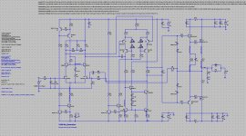
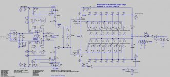
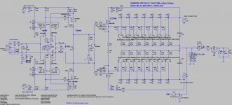
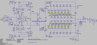
Here my schematic of 6th generation due all transistors are upgraded to modern components and easily buying.
// Mids are off due sound characteristics of 2SC2922 as it, if you try to replace by ON Semi ones, the mids will be better.
Regard,
// Mids are off due sound characteristics of 2SC2922 as it, if you try to replace by ON Semi ones, the mids will be better.
Regard,
Attachments
Last edited:
Proto amp is running with stable output stage bias, finally 😉
As VBE multiplier, I used the 2SC3964 bjt, specific designed for this purpose.
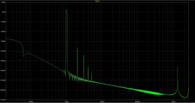
Here you can find current circuit, FFT profile 1W 8Ohm speaker load, PCB's designs and 10KHz square wave test into 8R. Compensation needs some further tweeking. Only compensation used at the moment are 2 7.5pF silver mica caps.
Next step is trying to determine open loop bandwidth, using the split feedback resistor option, mentioned on this forum a couple of times. Open loop bandwith can be changed using the VAS loading/feedback resistors from VAS output to base/gate of VAS devices.
Output stage is changed from the 2SC2911/A1216 MT200 to the MT100 package with same die, to be able to use 7 pairs output BJT's which increased class A power up to 12Wrms in to 8R.
Regards
As VBE multiplier, I used the 2SC3964 bjt, specific designed for this purpose.
Here you can find current circuit, FFT profile 1W 8Ohm speaker load, PCB's designs and 10KHz square wave test into 8R. Compensation needs some further tweeking. Only compensation used at the moment are 2 7.5pF silver mica caps.
Next step is trying to determine open loop bandwidth, using the split feedback resistor option, mentioned on this forum a couple of times. Open loop bandwith can be changed using the VAS loading/feedback resistors from VAS output to base/gate of VAS devices.
Output stage is changed from the 2SC2911/A1216 MT200 to the MT100 package with same die, to be able to use 7 pairs output BJT's which increased class A power up to 12Wrms in to 8R.
Regards
Attachments
you could use 12 pair of MJE15031,32 with 1 ohm emitter resistors at little to no penalty other then a new layout.
Nice design,
It seem you are using VMOS 2SK1530/2SJ201 as drivers. Do you compare to last version which used LMOS ECX10N20/10P20.
It seem you are using VMOS 2SK1530/2SJ201 as drivers. Do you compare to last version which used LMOS ECX10N20/10P20.
you could use 12 pair of MJE15031,32 with 1 ohm emitter resistors at little to no penalty other then a new layout.
Hi, yes, only if my rails were a lot lower. I'm using +-52Vdc for the output stage.
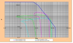
Enclosed is the SOA curve with 30! pieces of MJE15031 derated at 50°C. This output stage would "explode" with the first hard bass.
Attachments
Nice design,
It seem you are using VMOS 2SK1530/2SJ201 as drivers. Do you compare to last version which used LMOS ECX10N20/10P20.
Thanks,
Indeed, I've blown all my LFET's during tweaking of the VBE multiplier. As I had 6 pairs closely matched 1530/201 in my parts bin. I've thrown them in, all sounds fine. However, I can not compare the sound of the LatFets VS the audio VFet's.
Regards
derated at 50°C.
7 pairs of A1386/C3519 handle 28A (80% at 50C) at 50Vce, almost 4 times the dissipation of 15 pairs of MJE15031/MJE15032.
Nothing beats square mils, the same die area as 14 Sanken devices requires 46 MJE1503*
Last edited:
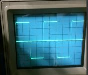
Square wave testing
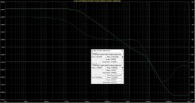
Played a bit with the frequency compensation and settled today at:
- 5pF Lag compensation
- 7.5pF compensation from Vas Out to Diff pair
Enclosed the several pictures made at 10kHz with different film cap values.
Up to 8R//68n square wave is as good as not affected. From 330n onwards overshoot and relatively good damped ringing is visible.
What is your thought about the square wave respons? Do I need to tweek it further, any advise?
Regards
Attachments

Sinus wave tests ==> distored wave form on higher freq
Hello,
I've build the B-build PCB for the front end. Square waves are still looking good as in previous post.
However when performing sinus wave testing, on higher frequencies the wave form looks heavilly distorted. Up to about 10Khz nothing is visible, on 100kHz and 200kHz a ugly looking wave form is generated near the crossover point.
Does anyone have an idea what causes this. Have never seen this before in my previous amps. This amp is using quite some Fet's in front end and driver section, are the capacity parameter playing me parts?
Attachments
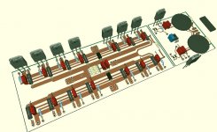
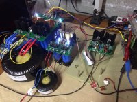
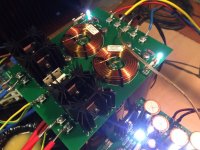
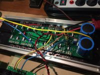
Music is playing from final PCB boards!
Output + driver PSU is ready
- 1kva toroid / Hexfred diodes dual bridge / 22000µf - 0.18mh 0.11R coil -
22000µf
Front end cap multiplier PSU is ready.
- 50VA toroid with FET cap multiplier
Front end is ready
- Jfet input stage cascoded with lateral TO220 Hitachi FET's and
IRF710/9610 VAS stage running at 30mA
- All resistors are takman metal film and NFB series resistor is charcroft Z-foil
Output+ driver stage and DC-servo PCB design is currently work in progress.
I am very happy with the quality of the PCB's (made by JLCPCB).
Attachments

Always nice to see others hard work playing music.
What is your arc welder driving?
I was wondering why you choose bjt ops vs a mosfets type?
As a comparison, here is a pic of 2 new Bob Cordell amp designs, a traditional all bjt with 2 pair of MJL3281/1301 and a DH-220C driving a pair of dual die lateral fets.
What is your arc welder driving?
I was wondering why you choose bjt ops vs a mosfets type?
As a comparison, here is a pic of 2 new Bob Cordell amp designs, a traditional all bjt with 2 pair of MJL3281/1301 and a DH-220C driving a pair of dual die lateral fets.
Attachments

You're slew-rate limiting I suspect. An amp designed for 20kHz doesn't have to handle the slewing of full power 100kHz signals.Hello,
I've build the B-build PCB for the front end. Square waves are still looking good as in previous post.
However when performing sinus wave testing, on higher frequencies the wave form looks heavilly distorted. Up to about 10Khz nothing is visible, on 100kHz and 200kHz a ugly looking wave form is generated near the crossover point.
Does anyone have an idea what causes this. Have never seen this before in my previous amps. This amp is using quite some Fet's in front end and driver section, are the capacity parameter playing me parts?
If this is visible before 25kHz or so then it indicates inadequate slewing for audio bandwidth.
I think its simply that the VAS cannot provide enough current to charge the gate capacitances at those rates. At the switchover point both
gate capacitances have to be charged rapidly, that's about 3nF or more to be charged several volts in very short order (sub µs) to switch
one device on and the other off - do the maths and you'll see 30mA is probably borderline for doing this. Adjusting the bias may help
this. What bias current are you using? MOSFETs tend to like 100mA or so.
You might do much better with standard BJT drivers which need far less current in these situations as there is little capacitance.
Last edited:
Always nice to see others hard work playing music.
What is your arc welder driving?
I was wondering why you choose bjt ops vs a mosfets type?
As a comparison, here is a pic of 2 new Bob Cordell amp designs, a traditional all bjt with 2 pair of MJL3281/1301 and a DH-220C driving a pair of dual die lateral fets.
Hi rsavas,
I'm having some tannoy reveal monitors for the moment. Once the amp is finished I can start saving for a decent preamp and speakers.
In my previous amp's I used lateral mosfets and the vertical 1530/201. After reading a lot of threads on bjt vs mosfet, I moved tonthe bjt side and am not regretting it.
Regards
You're slew-rate limiting I suspect. An amp designed for 20kHz doesn't have to handle the slewing of full power 100kHz signals.
If this is visible before 25kHz or so then it indicates inadequate slewing for audio bandwidth.
I think its simply that the VAS cannot provide enough current to charge the gate capacitances at those rates. At the switchover point both
gate capacitances have to be charged rapidly, that's about 3nF or more to be charged several volts in very short order (sub µs) to switch
one device on and the other off - do the maths and you'll see 30mA is probably borderline for doing this. Adjusting the bias may help
this. What bias current are you using? MOSFETs tend to like 100mA or so.
You might do much better with standard BJT drivers which need far less current in these situations as there is little capacitance.
Hi Mark,
Yes, I was thinking the same and are not bothered anymore by the not perfect sine wave at this output level and frequencies.
Vas vertical fet's are biased at about 30ma and 1530/201 driver fet's are biased at 110ma.
Fet drivers with a bjt output stage have always looked very interesting and have no plans in trying a triple bjt OPS. Parasound, Classe, accusound for example are using this principle also.
Regards
I have tried some kinds of output stage since i build my amp. I can confirm FET drivers sound better than BJT triple emitter. However in my case, the FETs as driver that are lateral MOSFETs.
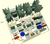
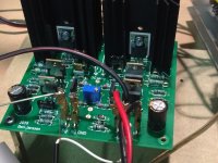
Fully build amp...but
Hi,
I've first build the OPS with only 1 pair of BJT output devices (2SC2922+ 2SA1216). Frequency compensation is finetuned to get nice square waves and stable amp (tested with 10meters of speaker cable and R//C loads.
Than I decided to mount all output devices = 7 pair 2SC3519 + 2SA1386 (same die as the 2922/1216). BUT then: when I am increasing bias current to reach the amp starts to oscillate heavely. Increasing C10 helps to stabilize it again.
(Output stage PCB is still prototype ans mounted on some old heatsinks.)
I haven't changed anything else but the output devices. LTspice is not confirming other GM and PM when chaging the amount of output devices.
Is anyone els knowing this phenomenen?
All info is highly appreciated. I'm near to completation and like to finaly start enjoying the music.
Attachments

You have a very beautiful chart, just now I saw it on the site. Consequently, the distortions also have such excellent parameters. R6 R7 R8 R9 these resistors can be removed. Distortion at small amplitudes will become even smaller, and at large amplitudes it is likely to remain unnoticeable.Hi,
I've first build the OPS with only 1 pair of BJT output devices (2SC2922+ 2SA1216). Frequency compensation is finetuned to get nice square waves and stable amp (tested with 10meters of speaker cable and R//C loads.
Than I decided to mount all output devices = 7 pair 2SC3519 + 2SA1386 (same die as the 2922/1216). BUT then: when I am increasing bias current to reach the amp starts to oscillate heavely. Increasing C10 helps to stabilize it again.
(Output stage PCB is still prototype ans mounted on some old heatsinks.)
I haven't changed anything else but the output devices. LTspice is not confirming other GM and PM when chaging the amount of output devices.
Is anyone els knowing this phenomenen?
All info is highly appreciated. I'm near to completation and like to finaly start enjoying the music.
As they say in Russia, an elegant aircraft flies beautifully.
Last edited:
What chart do you mean?
Having resistor there is sometimes very convenient for determine the current flowing there. 2r2 was the smallest value I could purchase from Takman metal film resistors.
Concerning the oscillations I'm having with running 7 pairs output devices: I'm measuring 4,8MHz oscillation.
Have no idea what the root cause is for this. Will first have a trial with doubling the base stopper resistors from 4r7 to 9r4, see what this brings.
I do not mean a diagram, but a beautiful scheme.What chart do you mean?
Having resistor there is sometimes very convenient for determine the current flowing there. 2r2 was the smallest value I could purchase from Takman metal film resistors.
Concerning the oscillations I'm having with running 7 pairs output devices: I'm measuring 4,8MHz oscillation.
Have no idea what the root cause is for this. Will first have a trial with doubling the base stopper resistors from 4r7 to 9r4, see what this brings.
Check in LTspice distortion greatly fall without these resistors R6 R7 R8 R9. Resistors for monitoring the current in LTspice can be put 0.00001 Ohm. And in the real circuit they are not needed at all, few people put them even in industrial amplifiers.
https://www.diyaudio.com/forums/att...ow-nfb-fet-front-bjt-ops-circuit-31072019-jpg
Last edited:
Test with higher base stoppers OPS
I added an extra 4R7 base stop resistor for each output device.
I gently increased the bias and from about 15mA throught the output devices, the amp started to oscillate again at about 5MHz.
When lowering the bias again I notice also oscillation only when the amplitude of the input signal is high when playing music, at lower amplituded/passages the oscillation stop again.
Any advise what to try next?
Attachments
- Home
- Amplifiers
- Solid State
- 2nd amp from scratch: Low NFB- FET front end - BJT OPS