Hello,
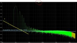
I've removed all unnessary parts and added step by step all of them again to find out what causes the sloped noise floor in the FFT analysis. High pass input filter and speaker load are the cause of the sloped noise floor.
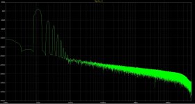
Without these the noise floor in the FFT is as good as horizontal.
I've made some pictures of the oscillations.
Interesting is that the first 10 to 20 seconds after start up no oscillation is present, it seems once the active components start to heat up, oscillation occur.
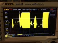
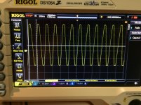
Below 2 pictures: on of a music signal with the oscillation bursts. The second picture is a close up of one of the oscillation bursts ==> 5Mhz oscillation.
I've removed all unnessary parts and added step by step all of them again to find out what causes the sloped noise floor in the FFT analysis. High pass input filter and speaker load are the cause of the sloped noise floor.
Without these the noise floor in the FFT is as good as horizontal.
I've made some pictures of the oscillations.
Interesting is that the first 10 to 20 seconds after start up no oscillation is present, it seems once the active components start to heat up, oscillation occur.
Below 2 pictures: on of a music signal with the oscillation bursts. The second picture is a close up of one of the oscillation bursts ==> 5Mhz oscillation.
Attachments
You make everything complicated.
There for only 15 minutes of work, not for three days.
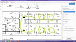
You have to do as I requested, and just look at the models at different stages of the cascades of the same noise. In this cascade, where the output will be the same picture as now, the cascade will be problematic.
There for only 15 minutes of work, not for three days.
You have to do as I requested, and just look at the models at different stages of the cascades of the same noise. In this cascade, where the output will be the same picture as now, the cascade will be problematic.
Last edited:
It's difficult for me to understand exactly what you mean i need to do.
But, the last page in the pdf document from post 101 shows the FFT without global NFB. This looks ok (I think) and while this is open loop, it means that the previous stages (or cascades as you name it), all behave decent.
But, the last page in the pdf document from post 101 shows the FFT without global NFB. This looks ok (I think) and while this is open loop, it means that the previous stages (or cascades as you name it), all behave decent.
For some reason, zip and pdf do not open, writes in size 0 kB. I can’t see what is there. The shape of the noise indicates a problem. That is, you can find a specific cascade and even the exact place with this very problem.
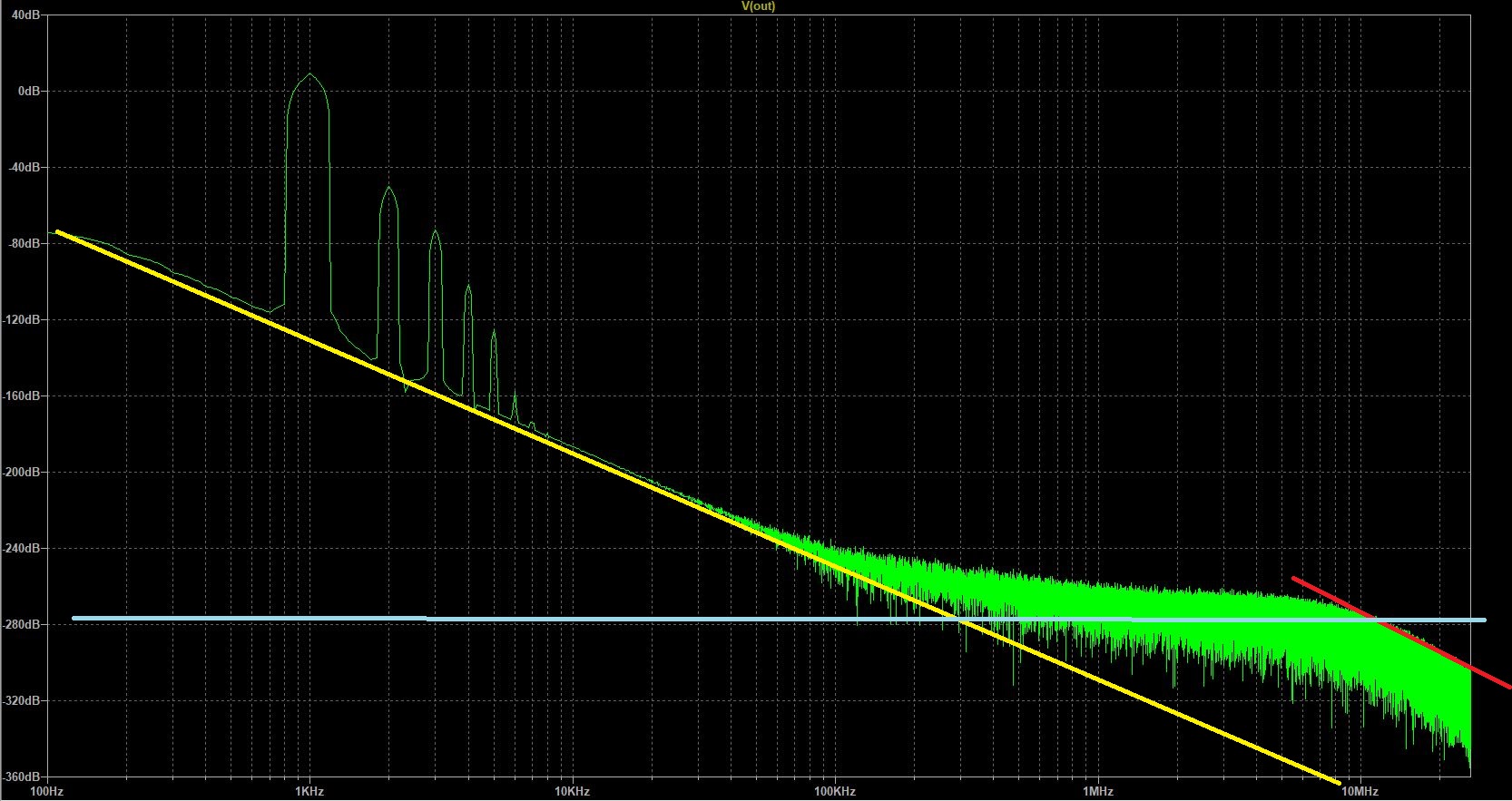
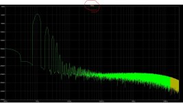
Here the red color is showing the problem.
Here the red color is showing the problem.
Last edited:
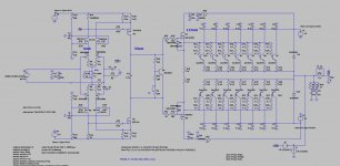
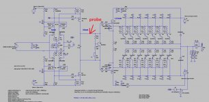
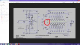
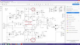
I'm trying to find out which part of the circuit is causing the slope according the red marked area in previous post. During open loop simulation all the wy down to the input stage. It seems that the output of the input stage (output node LTP on circuit below) already shows this sloped area. I stripped the entire input stage, removed; freq comp, decoupling, safety zeners, gate stoppers. What else can I do to find the root cause? The topology itself is proven design (Parasound for example). BTW: I've just managed to blew the entire output stage (14 pieces of Sanken bjt's, ):
Attachments
Hello Ben. You said that your amplifier was not generated when there was only one pair on the output stage. You can remove the extra transistors to make sure again.
It is better not to turn on the amplifier at all, until it is completely possible to determine the model. Can you name the approximate cost of all your kits along with transformers, boards, transistors, and more? You can still see the noise here.
It is better not to turn on the amplifier at all, until it is completely possible to determine the model. Can you name the approximate cost of all your kits along with transformers, boards, transistors, and more? You can still see the noise here.
Attachments
Last edited:
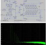
Below is the FFT from VAS output on location as per red arrow from above post. The knee-point is also here visible, entire noise-floor is slightly sloped. Yes, I need to replace all output BJT's and start agian with only 1 pair. This will take some time. During the sim's in pdf document a few posts back. Noise floor is nice horizontal, BUT this is in closed loop. See second picture (circuit + FFT)
Attachments
Last edited:
You can do everything in the model. Without a real amplifier. There should be no noise slope, why do you have it?
I asked to deal with this first of all. You probably have a filter somewhere again, maybe the one on the output.
You cannot determine who gives the high frequency tilt unless you remove all the filters.
I asked to deal with this first of all. You probably have a filter somewhere again, maybe the one on the output.
You cannot determine who gives the high frequency tilt unless you remove all the filters.
Last edited:
You have it all. The most powerful tool that shows everything - LTspice. This one has a dipstick. If I had your file, I would find you very quickly. But I will not recruit your scheme again. Your amplifier and model are faulty. You did not need to turn on a real amplifier just a model.
The last picture for analysis is good, is this a way out? Now you need to look at this point, which is indicated by a red arrow. I can not watch pdf on the specified site, I do not know why. Attach in .jpg
The last picture for analysis is good, is this a way out? Now you need to look at this point, which is indicated by a red arrow. I can not watch pdf on the specified site, I do not know why. Attach in .jpg
Last edited:
That picture is closed loop without any load on the output.The last picture for analysis is good, is this a way out? Now you need to look at this point, which is indicated by a red arrow. I can not watch pdf on the specified site, I do not know why. Attach in .jpg
Just simulated it again and measured on VAS out (red Arrow), please find circuit en FFT below.
I noticed that I only get a horizontal noise floor if NO output is connected.
What can you analyse out of this?
Attachments

Last edited:
Yes, 100% correct. But still very passioned about diyaudio.
Now that I think about it..when increasing the amount of output devices, I also added the extra MKT decoupling cap per output device and emmitter resistors.
Emmiter resistors are dale NS (non-inductive), these should be good. But I will test with removing the extra decoupling caps.
Now that I think about it..when increasing the amount of output devices, I also added the extra MKT decoupling cap per output device and emmitter resistors.
Emmiter resistors are dale NS (non-inductive), these should be good. But I will test with removing the extra decoupling caps.
Education is not that important. You can learn the basic things yourself. It is imperative to have engineering thinking. I have given you valuable things, but everything that you change makes them meaningless. Why then ask me what is in your scheme? Why did you return a negative review again or suddenly take off the load? And why did you again need an output filter to make it more difficult to determine where the real drop in the high frequency is?
Put emitter resistors, like all other amplifiers, and forget about their existence.
You did not find the reason? It looks like your driver is too good “better” than the parasound.
Put emitter resistors, like all other amplifiers, and forget about their existence.
You did not find the reason? It looks like your driver is too good “better” than the parasound.
You did not find the reason? It looks like your driver is too good “better” than the parasound.
Well, no, not the actual root cause.
However found some interesting facts:
1. tested again with only one pair of output devices: no oscillation, even with high output levels (80vpp)
-removing the decoupling caps, close to each output device makes the oscillation start sooner
2. 2pairs of output devices: oscillation visible with rather small output levels (15vpp). Now, when lowering the zobel network from 100n+10R to 100n + 5R, the oscillation is completely gone, even with high output levels.
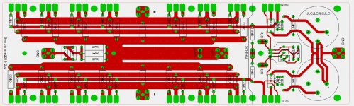
I don't think the PCB layout is the cause, while changing from 1 to 2 pairs of output devices changes nothing regarding currents throught PSU or speaker PCB traces. See OPS + driver PCB below. The small green dots are vias, here the pcb trace is on both sides of the board.
Have to do some more trial and error testing to find more parameters which have impact on the oscillation. Currently I also changed the emitter resistors to Futaba MPC74 type, this didn't made a change either.
Kind regards
Attachments

What does the board and the real amplifier have to do with it, even if the LTspice model shows a problem with excitation? In the model, do you think the tracks are also poorly divorced? I looked at the Parasound circuit and am just sure that this amplifier works well. Now look at your driver and compare.
Вest wishes.
Вest wishes.
Attachments
Last edited:
I'm aware of this difference.
Connecting the midpoint between the driver emitter resistors to the output and increasing base stoppers to 10R has a positive effect on the oscillation, however, it does not solve the problem. Oscillations stays visible on the scope during higher output levels.
Making this connection in LTspice make no difference, gain and phase margin do not change, nor does the noise floor changes when performing FFT analysis.
The reason I've chosen to not connect to the output is that according to simulation the drivers stay deeper biased into class A in high output levels/output current. Have no idea if it will make a difference in real life.
BTW, is wat not my intention to "clone" a Parasound. However, if I understand that the Parasound way is better than mine, I will offcourse change.
Last edited:
With all due respect to you, but your level can not be compared to the level of John Curl. He is a well-known developer, and you can’t repair your own amplifier.
Here's more about this, I also wrote to you. No one is putting equalizing resistors in field effect transistors. Even many do not apply in bipolar. Because they do not improve everything in the differential cascade.
It would be very reasonable if you first cloned a parasound into the LTspice.
Here's more about this, I also wrote to you. No one is putting equalizing resistors in field effect transistors. Even many do not apply in bipolar. Because they do not improve everything in the differential cascade.
It would be very reasonable if you first cloned a parasound into the LTspice.
Attachments
Last edited:
5Mhz = bad connection
Did read a few times on the forum that 5mhz (about) are in most cases bad connections. Wel, I just thought about that during the assembly of the front end, I did not solder the VAS heatsinks to their solder pads which are traced to the ground.
After soldering them (connection to ground) the oscillations depending on the output level are completely gone, this without any other change to the circuit.
Never thought that this would make such a difference.
During the troubleshoot phase I learned quite a few guide lines to take in mind during design of the PCB layout.
Now I see that there still is some small signal oscillation (not signal dependent), of 40mVpp 39,5mHz.
I read that the equalizing resistors are used to balance out the gm between a n & p channel jfet device. This reduces even order harmonics.Here's more about this, I also wrote to you. No one is putting equalizing resistors in field effect transistors. Even many do not apply in bipolar. Because they do not improve everything in the differential cascade.
- Home
- Amplifiers
- Solid State
- 2nd amp from scratch: Low NFB- FET front end - BJT OPS