Apparently, John Curl in his amplifier parasound decided differently. Because it is much more important that the overall negative feedback from the output covers all the transistors of the differential stage equally. https://www.diyaudio.com/forums/att...2nd-amp-scratch-low-nfb-fet-front-bjt-ops-jpgI read that the equalizing resistors are used to balance out the gm between a n & p channel jfet device. This reduces even order harmonics.
Last edited:
Ask John Curl, if he would do it the same now. Read what Bob Cordell has to say about it in his DH-220C re-design, which is what I was referring to using modern day LSK489,LSJ689 jfet pairs. I do not think that using a mosfet or a bjt as the cascode element makes any difference in this gm matching manner. It is splitting hairs in reality, just a technical discussion about why and why not.
I showed you John Curl's scheme, if you want to ask him about it, ask in person. I know for sure, since I was so taught that the output transistors distort an order of magnitude more than any input transistors. And I also know that in addition to the Parasound, the input differential stages in Rotel are designed in the same way, and only bipolar transistors are used there. In addition, I simulated the Parasound in LTSpice and again perfectly discovered this difference ...Ask John Curl, if he would do it the same now. Read what Bob Cordell has to say about it in his DH-220C re-design, which is what I was referring to using modern day LSK489,LSJ689 jfet pairs. I do not think that using a mosfet or a bjt as the cascode element makes any difference in this gm matching manner. It is splitting hairs in reality, just a technical discussion about why and why not.
Hi everybody
Bensen, try a capacitor 1 to 100nF between supplies positives and negatives as you can see in the NAD 3020. C637, C638 on positive supply, C629, C630 on negative
a little advice on repairing an NAD 3020a
Omitted them make the amplifier oscillate in this amplifier, may be in yours too. Your layout should offer very random current return ways. No offense, but its electronics and not electricity. The layout is crucial.
Regards
G.
Despite the advise to change the driver stage to an EF type I, I definitely would like to keep the EF type II after reading Douglas Self.
Actions to stop 5MHz oscillations:
1. increase output BJT base stoppers from 4R7 to 10R
2. Grounding VAS heatsinks
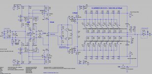
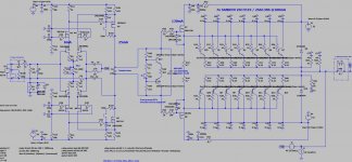
3. Feedback take-off point between zobel RC and output coil, physically about 10mm before the speaker connection on the PCB. Moving the feedback take-off point between output emitter resitors and the zobel RC, made the circuit more sensitive for oscillations. As drawn on the circuit below.
Actions to stop 40MHz 80mVpp
1. adding 110pF cap between VAS outputs (// to bias spreaderp), physically close to VAS devices. C11 on AS BUILD circuit below.
Other optimalisations
The previous single BJT bias spreader was to sensitive to adjust bias and was to much overcompensating.
I changed to a NPN + PNP bias spreader ==> adjustement is very accurately slichty overcompensating (good thing). Bias current is decreasing from 110mA to 100mA in a temperature range of 15°C to 50°C (bloody hot)
Output noise with shorted inputs.
On my scope (RIGOL DZ1104) I really can't see any difference between probing the ground or the output connection. This is with a 150mHz probe set 10X.
When listening directly with my ear against the speaker I can hear a very, very small humm.
I'm a happy DIY'er.
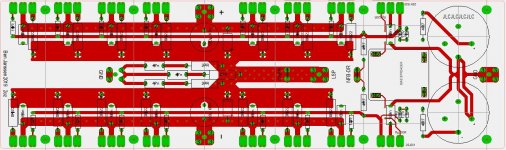
Now finalizing the output stage PCB's version 2.
Actions to stop 5MHz oscillations:
1. increase output BJT base stoppers from 4R7 to 10R
2. Grounding VAS heatsinks
3. Feedback take-off point between zobel RC and output coil, physically about 10mm before the speaker connection on the PCB. Moving the feedback take-off point between output emitter resitors and the zobel RC, made the circuit more sensitive for oscillations. As drawn on the circuit below.
Actions to stop 40MHz 80mVpp
1. adding 110pF cap between VAS outputs (// to bias spreaderp), physically close to VAS devices. C11 on AS BUILD circuit below.
Other optimalisations
The previous single BJT bias spreader was to sensitive to adjust bias and was to much overcompensating.
I changed to a NPN + PNP bias spreader ==> adjustement is very accurately slichty overcompensating (good thing). Bias current is decreasing from 110mA to 100mA in a temperature range of 15°C to 50°C (bloody hot)
Output noise with shorted inputs.
On my scope (RIGOL DZ1104) I really can't see any difference between probing the ground or the output connection. This is with a 150mHz probe set 10X.
When listening directly with my ear against the speaker I can hear a very, very small humm.
I'm a happy DIY'er.
Now finalizing the output stage PCB's version 2.
Attachments
Finalizing the design
Well, it looks like I can finalize the circuits, except for a decent soft start circuit with master/slave option for the 2 monoblocks.
Bias spreader is again more finetuned. OPS bias current is dropping about 5mA from cold to very hot (can't keep my hand on the heatsink for more than 5 seconds.)
The bias spreader will be a small seperate PCB, plugged on the OPS PCB using pin headers.
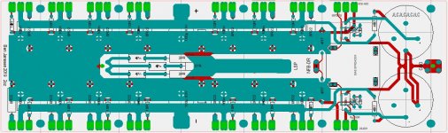
Below the as build circuit, PCB layout OPS (bottom layer + all layers) and 3D bias spreader.
My wife made a visit in my hobby area and mentioned once more that this amp sounds very lifelike (speakers are Tannoy reveal monitors)
Now I can focus on the hardware.
Well, it looks like I can finalize the circuits, except for a decent soft start circuit with master/slave option for the 2 monoblocks.
Bias spreader is again more finetuned. OPS bias current is dropping about 5mA from cold to very hot (can't keep my hand on the heatsink for more than 5 seconds.)
The bias spreader will be a small seperate PCB, plugged on the OPS PCB using pin headers.
Below the as build circuit, PCB layout OPS (bottom layer + all layers) and 3D bias spreader.
My wife made a visit in my hobby area and mentioned once more that this amp sounds very lifelike (speakers are Tannoy reveal monitors)
Now I can focus on the hardware.
Attachments

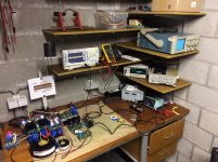
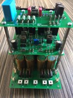
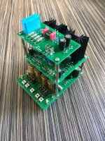
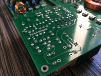
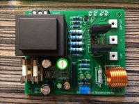
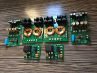
I'm in the process of cleaning all PCB's and making the sub assembly's.
Only PCB left is the big one for the output stage.
Here some pictures of the PCB cleaning been done and the assembly of front end cap multiplier + Front End + DC servo.
Bottom plate for the amplifier enclosures (2 monoblocks) have been ordered to start the actual building.
Some other parts of the enclosure (E.g. alu plates bolted to the heatsinks on which output stage pcb and output devices are mounted) are designed and ready to order.
regards
Attachments
I'm in the process of cleaning all PCB's and making the sub assembly's.
Only PCB left is the big one for the output stage.
Here some pictures of the PCB cleaning been done and the assembly of front end cap multiplier + Front End + DC servo.
Bottom plate for the amplifier enclosures (2 monoblocks) have been ordered to start the actual building.
Some other parts of the enclosure (E.g. alu plates bolted to the heatsinks on which output stage pcb and output devices are mounted) are designed and ready to order.
regards
Hi Bensen,
When you said DC servo what do you mean? It looks like SSR loudspeaker protection, am I right? Do you have spare PCBs for it?
BR Damir
Dear Damir,
I only have 2 pcb's left. The cost for shipment to you would be higher compared when ordering these together with other PCB's at for example JLCPCB.
Circuit (sort of) and gerber files can be found in this post and a few posts later.
https://www.diyaudio.com/forums/solid-state/318946-ssr-speaker-protection-15.html#post5841649
Kind regards
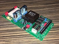
Update:
Soft start with the controller PCB were the last boards to arrive.
It has bin some years that I did something with CMOS logic and flipflop's, it was a surprice that the first version of the controller board worked perfectly.
Features of the controller board are:
1. press push button 4seconds to power amp on
2. another short push switches amp off
3. Power ON led flashes when solid state speaker relay isn't switched on yet
4. Amp is switched of when temperature switch opens, then Power ON led + Temperature led are flashing.
5. Amp is NOT switched on again when amp cools down after temp protection kicked in. You are required to disconnect the amp from the mains in order to switch on again.
The enclosure is work in progress as you can see.
Regards
Attachments
Drilling and tapping
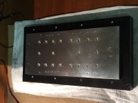
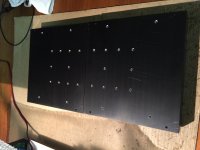
The intermediate plates (inbetween heatsink and output devices) have been delivered last week.
Today I quickly drilled and tapped all M5 holes for one monoblock.
I have drawn a drilling template on A3 Paper and used quite some cutting oil durring the drilling and tapping, luckily nothing has broken.
This was the mean reason to go for CNC machining intermediate plate, to avoid a lot of M3 threaded holes to be made by hand.
Tada… everything fits perfect.
But, should I use some thermal paste inbetween? The intermediate plate are super flat with a surface finish better than this of the heatsink. I'm afraid that using paste will have the opposite effect.
Attachments
Last edited:
Benson , How do you find the sound of this amp?
I Have been thinking of using IRF9610 and IRF610 to drive 2SC5200, 2SA1943 finals
I Have been thinking of using IRF9610 and IRF610 to drive 2SC5200, 2SA1943 finals
Well, I'm very happy with the sound. I can compare it to a Denan PMA700V and a few diy amps I've have build.
This one sounds offcourse the best. Enough detail, not to overly clear highs and mids. Soundstage is very wide (even when listening in mono). My wife (not really an audio lover) even notices that music is sounding very good, female voices hear very lifelike and true.
I compared the 6910/710 combo for the VAS with other Fet's and BJT's. But this 6910/710 did sound best.
For the driver's I'm using the 2SK1530 + 2SJ201. Latest shematic can be seen here:https://www.diyaudio.com/forums/sol...low-nfb-fet-front-bjt-ops-13.html#post5916541
The 710 may be a slightly better match for the 9610. it's curves are a bit different but the RDS on and input capacitance are very close.
It won’t take much of the thermal grease to fill any gaps between those parts, I would definitely use it however.
Very cool project!
Very cool project!
It won’t take much of the thermal grease to fill any gaps between those parts, I would definitely use it however.
Very cool project!
Thanks for the feedback,
I've made the decision to use some thermal paste, based on some visual checking of the flatness of the modushop heatsinks with a caliper. The two sides of the heatsink (left and right mounting face when fin's are vertically) are a bit deformed.
I've spread out very little thermal paste on the heatsink, after mounting the intermediate plate I saw thermal past coming out of the interface. This gave me a good feeling that all gaps are filled. I torqued all bolts from one side to the other side, in order to give the paste the possibility to "move" in between the two surfaces.
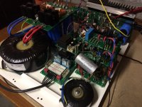
Hi,
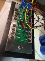
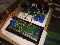
I've installed all 14 output devices and the Fet drivers for one monoblock.
The amp is playing at the moment in the basement, to check temperature versus bias current.
Observations sofar:
1: 24mV over 0R22 emitter resistors @18°C. Now 23.5mV at 50°C.
2: Variation between emitter voltages between the output devices is 3mV. This is to much to my taste, but I have enough parts to find good matches. (tolerance of emitter resistors is 0.5%).
Wiring and solder joints of output devices are NOT final 😉
Attachments
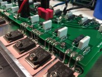

Why 7 pairs of output devices
I received a few question about why I use 7 pair of OPS devices, well:
1. I'm very conservative regarding SOAR-
2. I don't wan't to use VI limiter
3. I would like to have a about 10Wrms in class A
4. I would like to have it 2Ohm stable
Attached you can find a spreadsheet (based on David Eather his papers), which I made in 2003 and use to perform SOA calculations and simulations.
Have fun with it.
Attachments
Last edited:
- Home
- Amplifiers
- Solid State
- 2nd amp from scratch: Low NFB- FET front end - BJT OPS