Is there a fluctuation in the simulation model too? You are in the wrong place looking for a problem.I added an extra 4R7 base stop resistor for each output device.
I gently increased the bias and from about 15mA throught the output devices, the amp started to oscillate again at about 5MHz.
When lowering the bias again I notice also oscillation only when the amplitude of the input signal is high when playing music, at lower amplituded/passages the oscillation stop again.
Any advise what to try next?
C9 also needs to be removed in the model, parameters can also become better. Your circuit is like a Parasound. I modeled it before.
Last edited:
The AC analysis from the sim model doesn't change when altering the base stopper values.
In real life, my measurement tell me the same: same oscillation at same OPS bias current, both wiht 4R7 as 9R4 base stoppers. Yes, I need to look else for a solution.
In real life C9 = 5p and C10=8p. With these values I had a nice stable amp when only 1 pair of output devices.
Yes, indeed, it has suite some similarities JC1 OR HCA3500. It was not the intention. If you take a look at the beginning of this thread the design was much more complex. Due to all kind of issues the design has evolved to what is today. (Less is more)
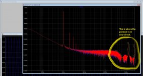
This is where the problem is in your circuit.
That's what you need to strive for
https://www.diyaudio.com/forums/attachments/solid-state/771148d1564353112-phase-harmonics-1-jpg
That's what you need to strive for
https://www.diyaudio.com/forums/attachments/solid-state/771148d1564353112-phase-harmonics-1-jpg
Attachments
Last edited:
Wrong information.
Tekst erased.
Below AC analysis of amp as-buid.
Tekst erased.
Below AC analysis of amp as-buid.
Attachments

Last edited:
I watched your circuits, the input stage is not changed. Show a new picture with noise like the previous one.Hi Gunfu, the FFT you are showing is from one of the previous iterations of this amp.
Here is AC analysis of the amp 'as build'.
It should ideally be like that. https://www.diyaudio.com/forums/attachments/solid-state/771148d1564353112-phase-harmonics-1-jpg
Last edited:
Here you have the noise analysis.
In the mean time what I have tested is:
1. increased C10 to 20p: result is better but oscillation not solved completely.
2. increased C9 to 6p: result is worse
3. added 3p...15p caps between gate and drain of FET drivers: result is the same
In the mean time what I have tested is:
1. increased C10 to 20p: result is better but oscillation not solved completely.
2. increased C9 to 6p: result is worse
3. added 3p...15p caps between gate and drain of FET drivers: result is the same
Attachments

I'm trying to figure out how to increase the scale of the FFT to 20Mhz. I seem to get no more than 2,6mHz
Hi, did you try to rise the value of fbk res R5 from 27k to 50k, 75k, 100k, etc to check if the oscillations will stop when even less gnfb factor?
I'm trying to figure out how to increase the scale of the FFT to 20Mhz. I seem to get no more than 2,6mHz
.tran 0 11m 1m 10n
.four 1K V(OUT)
.OPTIONS plotwinsize=0
.OPTIONS numdgt=7
.step param V list 2.83 40 55
Last edited:
I watched your circuits, the input stage is not changed. Show a new picture with noise like the previous one.
It should ideally be like that. https://www.diyaudio.com/forums/attachments/solid-state/771148d1564353112-phase-harmonics-1-jpg
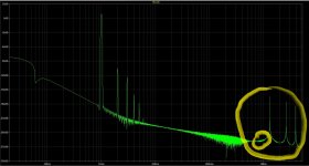
Managed to get data above 2MHz.
This doesn't look terrific. What to do to get rid of those "peaks" (-160dB)
Attachments

Hi, did you try to rise the value of fbk res R5 from 27k to 50k, 75k, 100k, etc to check if the oscillations will stop when even less gnfb factor?
Hi Pawel,
No I haven't, yet.
But remember, the was perfect stable with only 1 pair of output devices. Now that I have 7 pairs, troubles started. How I see it, this means that the amp itself is fine, but that possible something has to been done regarding compensation?
There seems to be a problem in this picture.
For starters, I would turn off the negative feedback and see only the noise. According to the data that I brought. # 89
For starters, I would turn off the negative feedback and see only the noise. According to the data that I brought. # 89
Attachments
Last edited:
Hi Pawel,
No I haven't, yet.
But remember, the was perfect stable with only 1 pair of output devices. Now that I have 7 pairs, troubles started. How I see it, this means that the amp itself is fine, but that possible something has to been done regarding compensation?
at what number of OT the oscillations started?
maybe this is multiplied junction capacitance related?
Good question 🙂
I did go directly from 1 pair to 7 pairs. I could test this, but it would be time consuming.
Yes, I'm thinking in the same way as you for the moment regarding junction capacitances.
I did go directly from 1 pair to 7 pairs. I could test this, but it would be time consuming.
Yes, I'm thinking in the same way as you for the moment regarding junction capacitances.
The problem with your amplifier is in a completely different place. You just activated it by turning on a few transistors.Good question 🙂
I did go directly from 1 pair to 7 pairs. I could test this, but it would be time consuming.
Yes, I'm thinking in the same way as you for the moment regarding junction capacitances.
There seems to be a problem in this picture.
For starters, I would turn off the negative feedback and see only the noise. According to the data that I brought. # 89
Hi GUNFU,
With your .tran function i'm getting following FFT result.
All peaks are gone.
Is this what you would like to see?
Attachments
No, I do not like this picture. I don't like the phase shift going on. And secondly, tell me, have you now disabled feedback as I asked or not?Hi GUNFU,
With your .tran function i'm getting following FFT result.
All peaks are gone.
Is this what you would like to see?
Why do you have input filters? They only interfere with the model and are completely unnecessary in the model.
The input filters distort the rest of the picture, it will be difficult for you to find the cause of the malfunction.
When you remove the feedback, the generator voltage also needs to be significantly reduced, to millivolts.
Last edited:
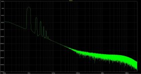
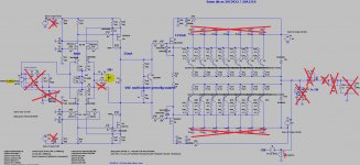
I bypassed the input filters and simmed without Feedback (ground to inverting input from input stage).
Please find FFT and modified circuit below.
Your troubleshoot knowledge and LTspice experience is clearly better than mine. Thanks for your help.
Please find FFT and modified circuit below.
Your troubleshoot knowledge and LTspice experience is clearly better than mine. Thanks for your help.
Attachments

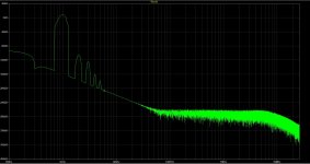
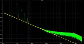
From the very beginning, the amplifier does not work correctly (yellow line).I bypassed the input filters and simmed without Feedback (ground to inverting input from input stage).
Please find FFT and modified circuit below.
Your troubleshoot knowledge and LTspice experience is clearly better than mine. Thanks for your help.
The amplifier noise not covered by feedback should be horizontal, parallel to the blue line. Apparently, capacitor C10 also creates negative feedback. All elements that twist the phase at this stage should be removed even at the output. They are not needed for modeling, they are only misleading. I would even close the resistor R3. You can always return the circuit. Now it is very important to make it so simple that the noise line is horizontal. But even now it’s already clear that the attenuation frequency from 5 MHz is very low (red line). And there, in your amplifier, there were self-oscillations.
In the next step, you need to find out where such a low recession (red line) occurs, this is definitely not an output stage.
Attachments
Last edited:
I crossed out in red everything that did not need to be placed in the model. Voltage sources are ideal here, so capacitors shunting them are not needed at all.
The output should be configured only for a load of 8 or 4 ohms, in this case, capacitors and inductors in our case are not required.
The output should be configured only for a load of 8 or 4 ohms, in this case, capacitors and inductors in our case are not required.
Attachments
Last edited:
- Home
- Amplifiers
- Solid State
- 2nd amp from scratch: Low NFB- FET front end - BJT OPS