That's indeed a good point. Have to watch the B+ doesn't go too high though.
Do you have a 10H choke? That would be a much better fit with the 50uF. Resonance comes down to 7Hz which is much better and also you will have a lot less ripple current through it due to the increased impedance it will impose upon 120Hz.
Member
Joined 2009
Paid Member
Back to square one with the choke.
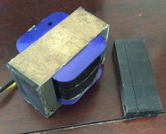
Now, what do I do with the varnish again ?
I have a small pot of Polyurethane, not a huge amount, can I 'paint' it on ? can I invert the choke and just soak the top half of it, the half with the I-laminations ? do I need to do any cleaning first ?
Now, what do I do with the varnish again ?
I have a small pot of Polyurethane, not a huge amount, can I 'paint' it on ? can I invert the choke and just soak the top half of it, the half with the I-laminations ? do I need to do any cleaning first ?
Attachments
Clen from dust and stuff, varnish wont adhere well on dust, it will peal after
The best is to dip it in a vacuum so the oxygen is removed , so the gaps between lamination are fully impregnated.
if you send it to me I do it right 🙂
The best is to dip it in a vacuum so the oxygen is removed , so the gaps between lamination are fully impregnated.
if you send it to me I do it right 🙂
Member
Joined 2009
Paid Member
It's a nice offer but two way postage already more than cost of the choke I am afraid !
I will try cleaning it, I have some acetone if that's safe to use ?
What if I dip and power-up to vibrate the varnish into place, is varnish in liquid form a good insulator?
I will try cleaning it, I have some acetone if that's safe to use ?
What if I dip and power-up to vibrate the varnish into place, is varnish in liquid form a good insulator?
Member
Joined 2009
Paid Member
Attachments

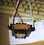
Like this ?
How long to keep it soaking ?
squeeze the bag some more til the whole choke is under the varnish...
look for bubbles, when there is none, lift the choke but keep inside the bag to drip,
then submerge again, do this at least three times, then let the varnish dry,
and then dip again, patience is a virtue here, let it dry for a week and then use it...
what i do in my traffo builds is to put it under the heat of the sun till temps are about 50*C
to let most of the moisture out and then dip it in varnish...
how did you find the smell? better do it in a well ventilated place....
Member
Joined 2009
Paid Member
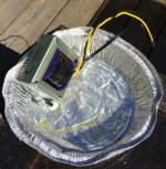
That is the plan, to squeeze the bag and let it stand in a tray in case it leaks. It is a zip lok bag so no smell 🙂
it is out of topic, it is a industrial vacuum impregnation machine which has also a vacuum pump to minus 6 times atmospheric pressure, it works quite nice
Hi all
I haven't posted in this thread but I have been reading it.
These days I am using a CCS loaded triode strapped pentode to directly drive 2a3 single-ended. Maybe I will post the circuit some day. There are a few good pentodes to chose from out there to chose from. Its exceptionally good.
You need to be careful with 6AV5GA. Some of them can't handle higher current. Best avoid the ones with holes in the plate... You will find that the triode curves are not entirely identical to 2a3 too. It helps to use an output transformer with 3.5k ohm if you want to use the 6AV5GA single-ended. Bias to around 65mA and you should be in for a treat.
Hope Ron is well.
Ian
Last edited:
Member
Joined 2009
Paid Member
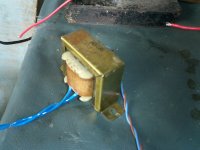
Well I followed all the instructions, 3 dips over more than 12 hour soak, let dry, dip again and now drying again.
Ian - my OPT is limited to 2k5 or 5k taps, so I will probably use the 5k taps. Not sure whether my 6AV5's are 'good' or not, there's a photo of them in post 306 where you can see the plates fairly clearly.
Ian - my OPT is limited to 2k5 or 5k taps, so I will probably use the 5k taps. Not sure whether my 6AV5's are 'good' or not, there's a photo of them in post 306 where you can see the plates fairly clearly.
Attachments
Last edited:
Hi Bigun
Those 6AV5GA's should be good. The internals look identical to some very nice RCA's and GE's I have. 5k should be ideal too - its actually what I used.
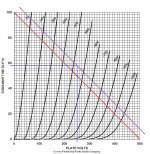
You can easily draw a 5k DC load line with plate at 250v and biased at -45V if you use the plate curves from Shannon Parks. Current should be around 50mA. Plate dissipation will be at around 12.5 Watts.
Depending on your power supply you could push up the plate to 300V, and bias at -55V to draw around 58-60mA like George did. Plate dissipation should be around 17.5 to 18 Watts. I found this to be pretty darn good.
Lots of work done on that choke. Hope it works out.
Ian
Those 6AV5GA's should be good. The internals look identical to some very nice RCA's and GE's I have. 5k should be ideal too - its actually what I used.
You can easily draw a 5k DC load line with plate at 250v and biased at -45V if you use the plate curves from Shannon Parks. Current should be around 50mA. Plate dissipation will be at around 12.5 Watts.
Depending on your power supply you could push up the plate to 300V, and bias at -55V to draw around 58-60mA like George did. Plate dissipation should be around 17.5 to 18 Watts. I found this to be pretty darn good.
Lots of work done on that choke. Hope it works out.
Ian
Member
Joined 2009
Paid Member
The purpose here is to follow along with Ron and his experiments, at least as far as trying out a couple of different driver options. My parts list is different from his so there will be some limits to how valid this is. I figure I will treat the 6AV5's as if they were 2A3's, using a 750R cathode resistor for somewhat traditional operating points.
Hi Bigun
I suppose you have already calculated your DC load line, your bias point and determined what your power supply needs to deliver.
If you mean Traditional in the RCA 2a3 specs sheet way, I can see a load line at -43.5 bias probably working. This translates to about 58mA and Vak of around 250. Plate will be at 293.5V and cathode at 43.5V
What have you designed your supply to deliver?
Ian
Attachments
Last edited:
I have some RCA, Sylvania, and Raytheon specimens. I also just ordered some 2.5k:8 OPT since Ron is using 2.8k:8
I too want to basically mimic what Ron is doing but with a few different 6AV5's and see how close they can compare.
For the time being I have some on the bench and plan to fire up a quick circuit to see how the bias up.
Va=250v
Rk=720 (two 10 watt 360R in series)
I just want to see how close the quiescent operating conditions are in comparison to what is predicted, then proceed.
Member
Joined 2009
Paid Member
What have you designed your supply to deliver?
I'm making use of what I have on hand, my power transformer and choke have been taken from another project. The power transformer dictates that I use a bridge rectifier with choke input filer in order to end up with something around 300V. The choke is only 2H and more would be better as it requires a decent current through the choke to have good regulation - around 150mA should do it which fortunately works out for a stereo amp.
I have a small cap between rectifier and choke whose value can be adjusted to fine tune the B+ voltage if necessary. I expect with the 1uF cap I have there right now that I'll end up with around 320V, less if I add an RC filter after the choke. So we have some room to negotiate the B+
Hi famousmockingbird
Well, I don't own a curve tracer, but was able to do point measurements with my calibrated AVO MKII and Shannon Park's triode curves were pretty close to my samples.
I think you will see that the load line is a bit steep for 2.5k - it is not as linear as 2a3 but you probably know that...
Since you want your Va ~250V, and your cathode resistor is already determined to be 720 ohms you must have a good idea of how the load line will look you will probably find the 6AV5 will draw a little over 50mA and the Vk will settle in at 37V - Vak will probably be 215V+37V = 252V - Also kind of "classic" values for 2a3.
Your 6AV5 specimens might be different, but it would be still a good idea to plan for ~50mA current draw for each output tube in your power supply. If this is completely obvious to you, then maybe it will still be a useful read for someone else on this board...
Ian
Attachments

Last edited:
- Status
- Not open for further replies.
- Home
- Amplifiers
- Tubes / Valves
- 2A3 driver